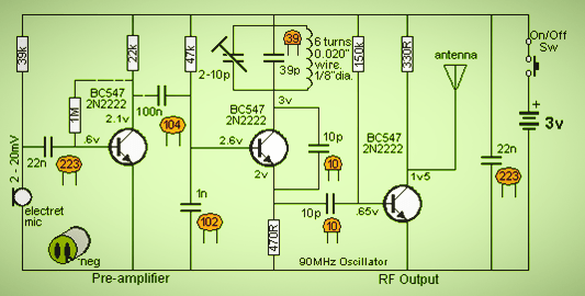
The 3 transistor FM transmitter circuit will be ranging about 100-meter distance. At the low cost, you can build this circuit easily. Generally, the FM transmitter uses VHF radio frequencies from 87.5 to 108.0 MHZ you transmit and receive the FM signal.
The FM transmitter is a 3 transistor circuit. The frequency modulation (FM) transfers, the information through the frequency of the carrier wave according to the message signal. This transmitter complies the most excellent range with less power (3v). the performance and working of the audio transmitter circuit depend on the induction coil and variable capacitor this article will explain the working of the FM transmitter circuit and with its application.
What is an FM transmitter circuit?
This FM transmitter is a low power transmitter (100-meter range) and it uses FM wave from transmitting the sound. This transmitter transmits the audio signals through the carrier wave by the difference of frequency, that carrier wave frequency is equivalent to the audio signal of the amplitude, and the FM transmitter produces the VHF band at the frequency of 88 to 108.0 MHz.
Circuit Diagram
The FM transmitter contains
- Microphone
- Audio preamplifier
- Modulator
- Oscillator circuit
- RF amplifier
Working
The circuit diagram shows the FM transmitter circuit and the required electrical and electronic components for this circuit. The power supply of 3-volt, resistor-capacitor, trimmer capacitor-inductor and transmitter, and antenna.
It is considered the microphone to understand the sound signal and inside the might, it contains a capacitive sensor reproduce according to the vibration to the change of air pressure and the AC signal.
The formation of the oscillating tank circuit can be done through the transistor BC 547 by using the inductor and variable capacitor. The transistor used in the circuit is an NPN transistor that’s used for general purpose amplification.
The current passed Through the inductor and variable capacitor then the tank circuit will oscillate at the resonant carrier frequency of the FM modulation. The negative feedback will be e the capacitor connect in the transistors emitter and the collector to the oscillating tank Circuit.
To generate the radio frequency signals, The FM transmitter circuit requires an oscillator circuit. The tank circuit (oscillator circuit ) is derived from the LC circuit ( inductor and capacitor ) to store the energy for oscillation. The inputs the audio signal from the mic passes to the base of the transistor with modulation.
The variable capacitor is used to change the frequency of the circuit. modification to the FM frequency the modulated signal from the antenna is radiated as radio wave at the FM frequency band. The antenna is a copper wire of 20 cm long and 24 gauge.
Application of FM transmitter device
- The FM transmitter is very easy to use and the low price
- The efficiency of the transmitter circuit is very high
- It has a large operating range ( 100 meters and above)


yes go through the link to see 3 transistor based FM transmitter circuit