Make 100 watt power inverter at home easily. you will get the free circuit and PCB layout here. its a 12 volt battery inverter and it will convert 12v dc to 12v ac supply with 100w output power. 12v dc to 220v ac inverter circuit.
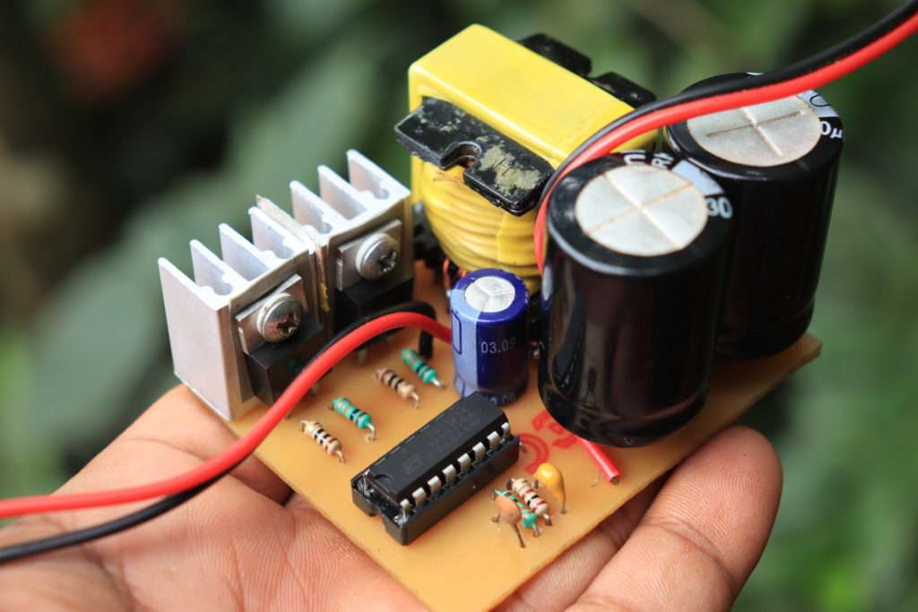
The simple inverter working based on the popular switching ic of SG3525. its a 16 pin plastic packaged oscillator ic can produce high-frequency signals on the output pins. The sg3525 ic will produce low and high-frequency ranges.
it is a simple inverter circuit. the circuit is designed with high-frequency output. you can use bulbs, CFL, mobile charger, laptop charger, etc ( you can not use fan or high power electrical devices it may burn your mosfets.)
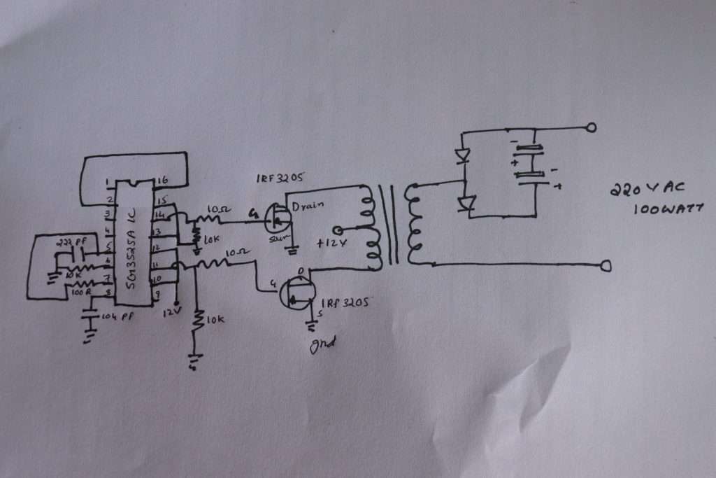
Circuit Diagram
Components Required
- Sg3525 ic ————————-1
- IRF3205 mosfet—————2
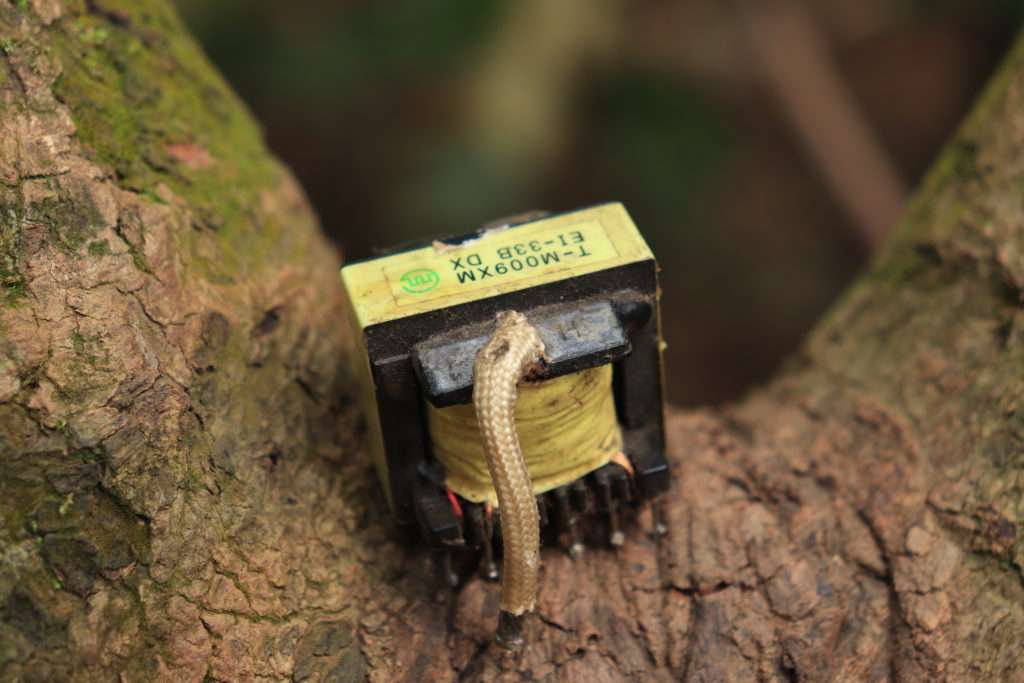
- EI33 Transformer ( re-winded )
- 330uf/250v capacitor————–2
- 1000uf 25v capacitor————–1
- 222 pf ceramic capacitor———1
- 104 pf capacitor———————-1
- 10k resistor —————————3
- 10 ohms resistor———————2
- 100 ohms resistor———————–1
- 16 pin ic socket —————————1
- FR107 diode ——————————–2
Winding Transformer
Take the EI33 ferrite core transformer from the old SMPS board. disassemble the transformer ( remove all coil from the former ). Then take the 19 SWG copper wire and take 2 wires. wind the wire 4 turns + center tapping and again 4 turns.
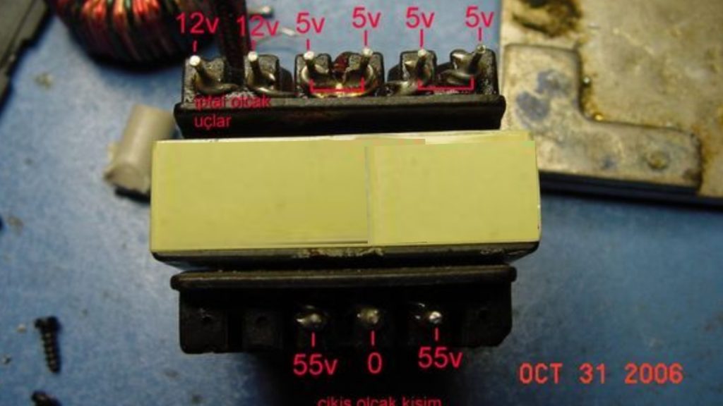
wind the secondary wire using 23 SWG copper wire wound the 90 turns on the former. and connect all the connections properly and solder it.
Working
The resistors and capacitors soldered in the ic pin number 5, 6,7,8 will produce high-frequency signals and the signals will amplify the IRF3205 MOSFET. The connected ATEX transformer will produce 220v ac supply output. SG3525 50hz 1500 watts inverter circuit diagram and PCB layout

pls sir, I built an inverter circuit of 220v AC, 12v DC, 500Watts, but having problem with the transformer. pls sir help in in with the following:
1. number of turns at the primary
2. number of turns at the secondary
note: the secondary side had a center tap
you can e-mail me:
thankgodchikere8 @gmail.com
use Ei33 or Ei35 transformer core
primary turns 3+3
secondary 90 turns