In this Article i’m going to introduce the PIC16F72 sine wave inverter circuit diagram and also the programming Hex code. So if you are searching in lot of website for the proper explanation and the designs of this ? Now you are in the right website post. Here you will get the complete ideas about this Pure sine wave inverter project.
Features and specifications
| DC battery specifications | 12v 180AH Lead acid |
| Inverter output voltage | 230v AC (+2%) |
| Inverter Operating Frequency | 50Hz ( similar to grid ) |
| Inverter output wave form | Pure sine wave |
| Harmonic distortion | Less than 3% |
| Inverter efficiency | 85% for the 12V system |
| Inverter protections | low battery shutdown overload shutdown output short circuit shutdown |
| Low battery indication | Beep start at 10.5v and the inverter shutdown at 10v DC remaining in battery |
| Overload protection | Beep starting at 120% Load |
| Led indications | Low battery Overload Charging Main on |
| Circuit spec | PIC16F72 microcontroller based circuit with H bridge inverter oparations. |
| Charging setup | Mosfet based PWM charge controller. 2 mode of charging boost mode & absorption mode. |
| DC fan | Fan installed for the internal cooling during the working. |
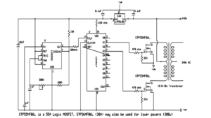
Circuit Diagram
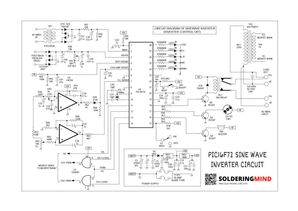
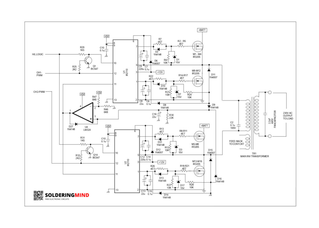
H Bridge Mosfet Section
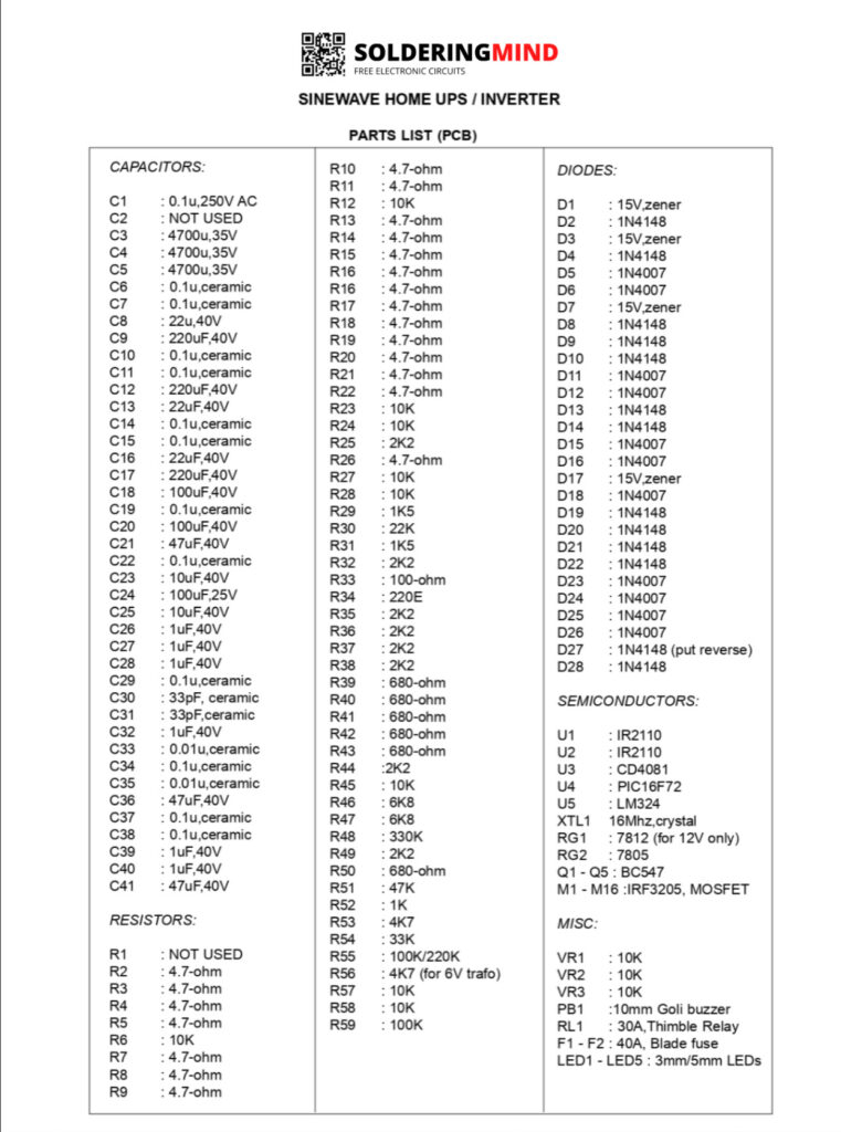
Components Required
Low Battery Indication
During the grid current on state that means the main on time the charging will occurs if the voltage is less than 11 voltage. The battery charging system is working based on the SMPS topology. To charging the battery the mosfet and the inverter transformer working as a boosting converter. The main on time the mosfet is acting as like a diode.
The primary coil is acting as the inductor. while the mosfets gets on and off time the energy has to be stored and released from the primary coil. Then the AC voltage is rectified and it will get rectified inside the mosfet and the battery get charged.
Over Load Protection
The one of the important feature is overload protection. If their is no overload protection in the circuit it make big problems as like mosfet burning and inverter board damage. here the inverter gets shut down if the load is above 130% and also giving the alert in 120% load.

Hi Akhil, I am from Kenya East Africa, could you please post another pure sine wave inverter circuit based on PIC30f2010. Thanks in advance
Sure thanks
pic16f72 based inverter technology
programming based inverter
sir in this circuit is zero detect circuit added, becausev without that there is sound on mains shifting
i am newbie electronic hobbyist ,your site has such a nice and helpful contents. keep the good work ,thank you
Amazing comments this will definitely encourage me to do more contents thanks
Kindly post the source code for the above pic iñverter
Already available in my site please check it