Build FM transmitter circuit – Building a cool project I always wanted to create an FM transmitter with a good range I have always been enjoyed by some of the applications of the transmitter, especially when I was young children and like everyone else spends most of my time imagining how to have some of the equipment and device used in spy movies.
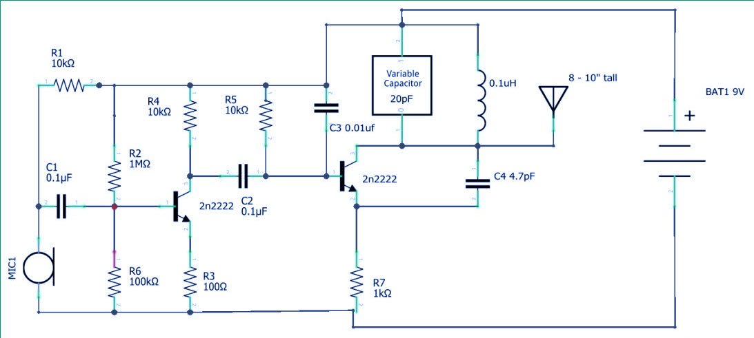
Circuit diagram and explanation
I am going to share some ideas about how to build your own FM transmitter easily and believe me it works perfectly. you can also make a simple Fm transmitter using one transistor
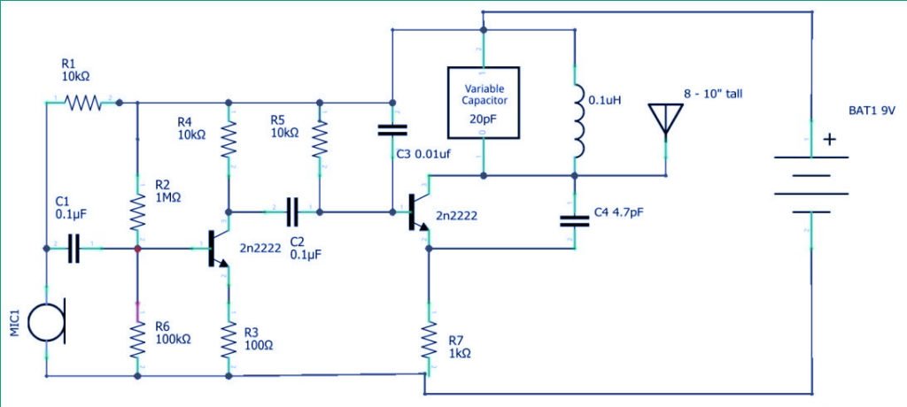
The audio output signal from the microphone is very small. The first transistor performs the job of amplifying the signal to a good level, for transmission. After amplification as described here the next stage of the transmitter is modulation at this stage the amplified audio signal is then mixed with the carrier frequency at with which the signal is to be transmitted.
This carrier frequency can be varied using the (20 PF) variable capacitor connected with the inductor. The typical frequency band of the particular design is in between the 88 Mhz – 108 MHz. There is no visual output to recognize the exact frequency is produced at which the transmitter is working.
Components Required
- 2n 2222 NPN transistor – 2
- Condenser mic or audio jack
- 100 NF ceramic capacitor
- 10nf ceramic capacitor
- 4 PF ceramic capacitor
- 100-ohm resistor
- 10k resistor
- 100K resistor
- 1 m resistor
- Variable capacitor
- 18 – 22 copper wire
- 9-volt battery
At this time it is important to say that this is being done experimental and learning purposes only. The law of certain countries prohibits unauthorized broadcasting it is very important to keep the FM transmitter at the low range and ensure it must be built within the limits of your country and do not make harassments to the public. and I am not responsible for the issues.
Working of FM Transmitter
FM transmitter is a device that uses the principle of frequency modulation to broadcast sound supplied to its input. typical FM transmitter designs usually in
- Sound input
- Preamplification
- Modulation
- Transmission
The signal strength of audio input into the transmitter is usually low therefore an RF amplifier is usually used to bring the level up. The desired frequency for transmission the carrier frequency is generated using an oscillator circuit and mixed with an audio signal to create the modulated signal.
The modulated signal is then passed through a power RF amplifier. at the transmission, stage to create low impedance matching with the antenna. you will need to adjust your FM receiver knob to ( radio ) within the range of The frequency to get the signals.
The frequency at which the transmitter is transmitting after modulating the audio signal with the carrier frequency/ The signal is then sent out through the antenna. The inductor is made by winding 8 to 10 terms of 18 to 22 gauge wire around a 1 by 1/4 inch former. Which can be represented by a pencil.