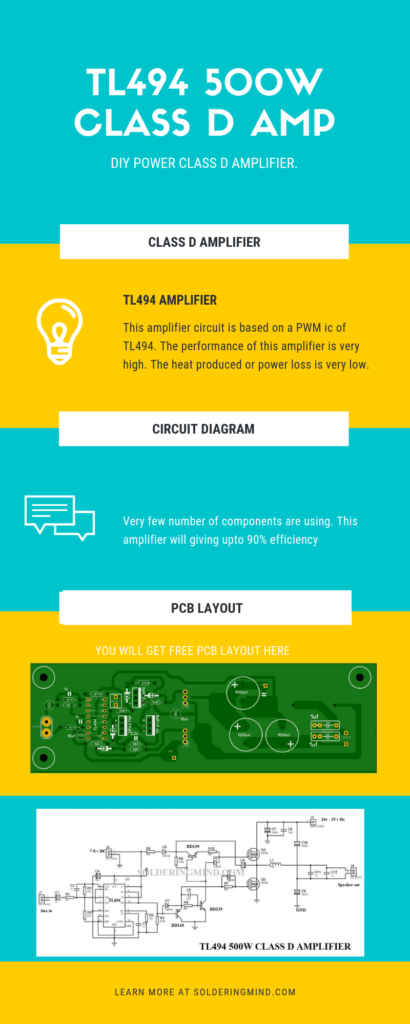
DIY 500w Class D amplifier circuit using TL494 ic. it is a class-d tl494 switching amplifier with high efficiency. You can use it as a car sub amp. The TL494 is a PWM ic will provide a high-quality signal that helps to generate high-quality audio signals.
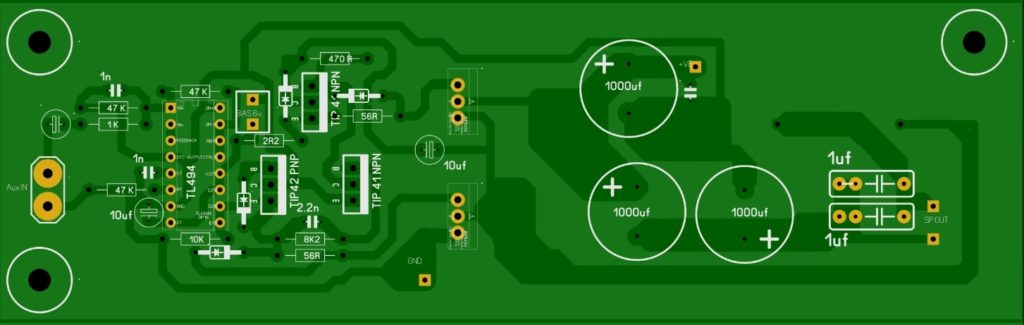
The circuit diagram and free PCB layout will be available here. if you want to make this amplifier board just download the PCB layout pdf file print it on glossy paper and do it yourself.
500W TL494 Class D Amp Circuit Diagram
TL494 amplifier circuit and free PCB layout.
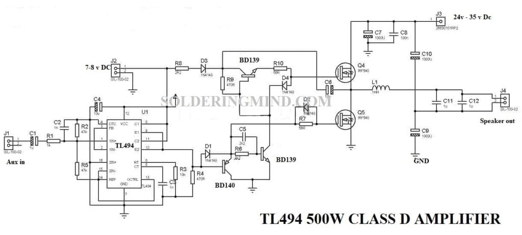
The circuit is a simple and highly efficient amplifier circuit that will provide up to 500 watts of output. The PWM will provide the signals to the comparator and process the audio signals on the output stage.
You also check 200 watts audio amplifier circuit
Working of class D amplifier
The typical class d amplifier consists of a sawtooth waveform generator circuit. comparator, switching circuit, and a low-pass filter section. The sawtooth waveform generator will produce a high-frequency sawtooth waveform for sampling the input audio signals.
The comparator’s job is to mix the input signals with the sawtooth waveform. The switching circuit is doing its job of providing the current and voltage gain which is essential for the amplifier circuit. Low pass filter this circuit will filter out the unwanted signals from the switching circuit.
Components required
- Tl494 – 1
- IRF 540 MOSFET – 2
- 1000uf 63v capacitor – 2
- 1000 uf 50v capacitor – 1
- Bd 139 transistor – 2
- Bd 140 transistor – 1
- 1N4148 diode – 3
- 1uf capacitor – 1
- 10uf capacitor – 2
- 1n capacitor – 2
- 152 pf capacitor – 1
- 1k resistor – 1
- 47k resistor – 2
- 10k resistor – 1
- 470-ohm resistor – 2
- 2R2 resistor – 1
- 8k2 resistor – 1
- 2n2 capacitor – 1
- 56-ohm resistor – 2
- power supply ( separate power supply for bias )
The download links are given here, you can download the complete file to build your own amplifier.
You may also like 1000 watts audio amplifier circuit

Just have a quick question about the 152pF capacitator. Why is it useful in this circuit and where do I connect it? Thanks for the answer, I really like this project of yours!
It works very well.Thanks 😊👍
You are welcome my friend
I have build tl494 500 watt class d as per the diagram but when I increase the voltage more than 20-0-20 dc the mosfet irf540 getting extremely 🥵 can any one suggest regarding this problem. Sound is very clear and working well in the 20-0-20 voltage range. Can any one solve my prolem. My contact no. Is 9439630828.
I have not built this yet, but the mosfets need heatsinking, even though switched, under load these will still get quite hot. Just run the math on a 77mohm fet at full current.. The package is excellent so a heatsink will probably sort you out. I have seen posts that the inductor also gets hot, but as you may see the resistance on one video showed 0.1 ohm so that is not surprising either as it takes full current.
I do aim to build this myself …. but i need a better power supply first!
I have now built the unit with a large heatsink, and yes the output 540’s run very hot and there appears to be low efficiency which aligns with this. I will continue to tinker with this to see what is up.
This circuit have signal noise
I don’t see the 152pf capacitor in the pcb or in the diagram
Where you use 152pf capacitor? i don’t see in the pcb?
This is very nice board
where you have connected 152 pf capacitor
Can someone send me the correct circuit diagram because I built this one and it does not work at all.
What is the power supply current rating?
Can I use other MOSFET such as irf240n and power supply 80v
i didn’t tested it
can i increase mosfet supply to 70v
Can you provide specification such as:-
-Input sensitivity
-Gain at 0db
-THD @ 100hz,1k,10k spectrum band
-Frequency response graph
-Signal to noise
YOU HAVE NOT MENTIONED ABOUT THE INDUCTOR COIL IN DETAILS…
The inductor coil ranging from 22uh to 35uh
I set this up so the sound is very low What’s
Froblums
increase the input voltage
I made this circuit already but the gain is very low. After increased the volume it start distorted. And what is the minimum voltage for this circuit?
Do you have the calculations of all the components you used in this project or not? If you can give me, doing a huge favor?
in the circuit diagram, all components are mentioned clearly
Class D vol max kok bret – bret
it’s working the working video is available in my youtube channel of SCHOOL OF TECHNOLOGY. The old pcb of tl494 having some error so i designed my own pcb then the problem was solved and working fine.
You stole that circuit from elcircuit.com
The given circuit is the same but the designing of the PCB is not the same. I found some error in elcircuit blog so I decided to rectify that one, so i uploaded this with my own ideas
Can u give ur contact i have lot of question about that circuit
contact me through contact us fourm
it works wells, this circuit??
Yes
Thank you bro i think you also subscribed to my website
yah sure I will try