TL494 is a popular PWM signal generating IC. Which is most common in SMPS circuits and inverter circuits. In this article sharing important information’s of TL494 Datasheet, Pinout and application circuits.
What is TL494 IC?
The TL494 is a pulse width modulation control IC. Most common in switch-mode power supplies, DC-DC converters, and other regulated power systems and High-frequency inverters. It integrates essential components, including two error amplifiers, a precision 5V voltage reference, an adjustable oscillator, a dead-time control comparator, and dual output transistors capable of sourcing or sinking up to 200 mA.
The TL494 supports both single-ended and push-pull output configurations. Its internal oscillator can be configured for frequencies up to 300 kHz, and the built-in dead-time control ensures safe operation by preventing the simultaneous conduction of both output transistors. With a supply voltage range of 7V to 40V and good thermal and short circuit protection, the TL494 is ideal for applications requiring stable and efficient power conversion.
Features
- Complete pulse width modulation and power control circuitry on a single chip.
- In built two internal error amplifiers for flexible feedback control.
- On chip adjustable oscillator with external RT and CT.
- Internal 5V reference regulator with ±5% accuracy.
- Output control allows selection of single ended or push pull operation.
- The output transistors capable of sinking or sourcing up to 200 mA.
- Dead time control input for setting minimum off-time.
- Internal circuit prevents the double pulsing of outputs in push-pull mode.
- Common mode input voltage range is 0.3 V to VCC 2 V.
- Generating frequency range is 1 kHz to 300 kHz.
- Synchronization capability for multiple TL494 IC.
- Short circuit protection on reference output.
- Operating temperature range: 0°C to 70°C .
TL494 Pinout
The TL494 PWM IC has 16 pins, 8 pins each sides of the IC. To count the number of pins, you need to hold the IC straight and the Notch coming in up position. Then hold the IC and count the pin from the left side, marked with any circle and the first pin is pin 1 to and follows the end to pin 8 and the other side pin number 9 starts from the bottom right side of the IC. The TL494 pwm controller IC Pinout diagram and its pin descriptions are given below,
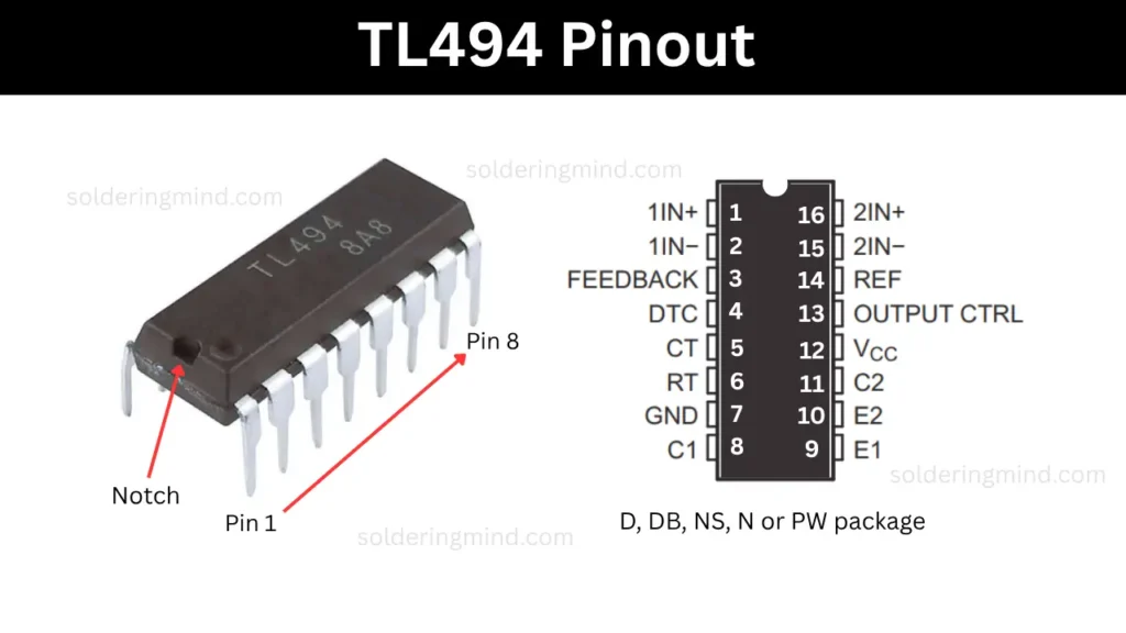
Pinout Configuration and Functions
The TL494 IC pinout configurations and functions of each pins are listed below in a table,
| Pin No. | Pin Name | Type | Function |
|---|---|---|---|
| 1 | 1IN+ | Input | Non-inverting input of error amplifier 1 |
| 2 | 1IN− | Input | Inverting input of error amplifier 1 |
| 3 | FEEDBACK | Input | Feedback input to control pulse width |
| 4 | DTC | Input | Dead-Time Control input; adjusts minimum dead time |
| 5 | CT | – | Oscillator timing capacitor terminal |
| 6 | RT | – | Oscillator timing resistor terminal |
| 7 | GND | – | Ground |
| 8 | C1 | Output | Collector of internal transistor 1 |
| 9 | E1 | Output | Emitter of internal transistor 1 |
| 10 | E2 | Output | Emitter of internal transistor 2 |
| 11 | C2 | Output | Collector of internal transistor 2 |
| 12 | VCC | – | Positive power supply |
| 13 | OUTPUT CTRL | Input | Chooses between single-ended or push-pull output operation |
| 14 | REF | Output | 5V reference output (internal regulator) |
| 15 | 2IN− | Input | Inverting input of error amplifier 2 |
| 16 | 2IN+ | Input | Non-inverting input of error amplifier 2 |
TL494 Application Circuit
This given circuit diagram is configured to generating variable duty cycle and frequency. The generating PWM signal is used to control the DC motors and LED lights based on the requirements. very few number of external components are used in this circuit. The 10K and 2M potentiometer can able to adjust the duty cycle and output frequency by adjusting its values. The circuit diagram and components list are given below,
Circuit Diagram
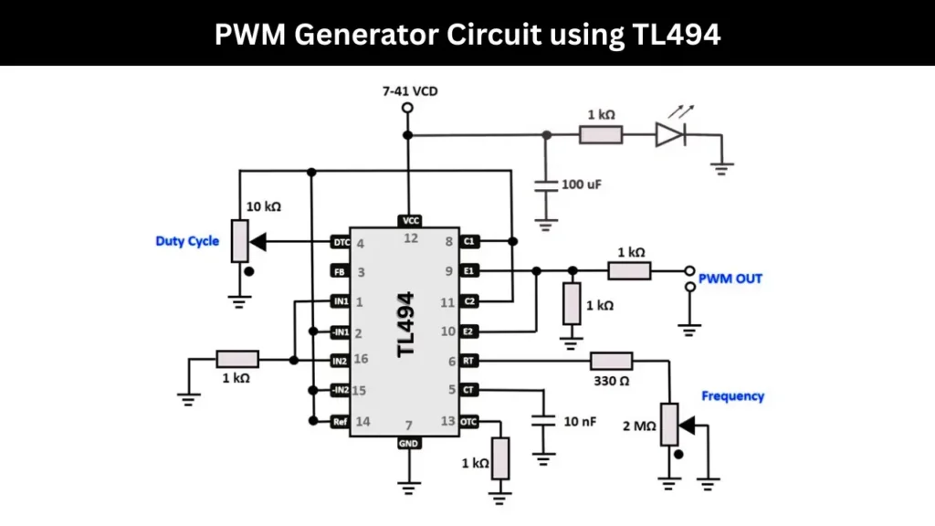
Components Required
To build this circuit you need electronic components, so the required electronic components list in given in the table below,
| Component | Quantity |
|---|---|
| TL494 | 1 |
| 10 kΩ potentiometer | 1 |
| 1 kΩ | 1 |
| 1 kΩ | 2 |
| 330 Ω | 1 |
| 2 MΩ potentiometer | 1 |
| 1 kΩ | 1 |
| 10 nF (0.01 µF) | 1 |
| 100 µF / 25V or higher | 1 |
| Standard 5mm LED | 1 |
| 7V to 41V DC | 1 |
How It Works
The IC pin number 5 and 6 are the PWM frequency controlling pins. This is depending on the value of capacitor and resistor connecting to it. You can adjust frequency using the 2 MΩ potentiometer labeled “Frequency.”
The Pin 4 is connected with a 10 kΩ potentiometer which will adjusts the duty cycle. This will changes the on/off ratio of the PWM signal. The Output signal is taken from the pins of E1 and E2.