The MPSA14 is a 30 V, 500 mA high-gain NPN Darlington transistor. This transistor is designed for signal amplification and low-power switching circuits. This transistor’s internal structure consists of two transistors, so it gives high DC current gain. In this article, I’m sharing the pinout and equivalent of the MPSA14 transistor.
MPSA14 Transistor Pinout
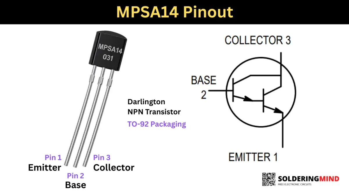
To check the pinout of this transistor, you need to hold the transistor flat labelled side facing to you and the three pins are pointing down. Then count the pins from left to right as Pin 1 Emitter, Pin 2 is Base and Pin 3 is collector.
MPSA14 Pin Configuration and Identification
| Pin Number | Pin Name | Symbol |
|---|---|---|
| 1 | Emitter | E |
| 2 | Base | B |
| 3 | Collector | C |
MPSA14 Transistor Specifications
- Transistor Type is NPN Darlington.
- DC Current Gain is Minimum of 10,000 and up to 20,000.
- Maximum Collector Current is 500 mA (0.5 A).
- Maximum Collector Emitter Voltage is 30 V.
- Maximum Collector Base Voltage is 30 V.
- Maximum Power Dissipation of this transistor is 625 mW.
- Transition Frequency is 125 MHz.
What Type of Transistor Is the MPSA14?
This MPSA14 NPN Darlington transistor comes in TO-92 packaging. high current gain is the main feature of this transistor.
Equivalent or Substitute Transistors
If you can not find the MPSA14 in stores you can go through the substitutes. You can use 2N5308, BC517, BC617, MPSA13, KSP14 as the equivalents. But the MPSA13 have less DC current gain of upto 5000. Always check the specifications and pin arrangement before replacements.
Important Precautions When Replacing MPSA14
The MPSA14 has 30V and 500mA characteristics. The packaging of this transistor is TO-92, so you need to be careful when replacing it with random NPN Darlington transistors. While choosing, do not exceed 30 V and keep the load current under 400mA. Pinout matching is the second important factor. So consider these before substituting.
How the MPSA14 Darlington Transistor Works
The internal structure of this transistor consists of two NPN transistors connected to each other. The first transistor’s emitter is connected to the base of the second transistor. Both collector pins are tied together, and it is called the collector.
The emitter is the second transistor’s emitter pin. This setup increases the overall current gain and improves tiny signal amplification to high gain.
Applications
- Used in sensor circuit to amplify tiny signal to large current.
- Pre amplifier section to improve audio gain.
- Also used in common switching circuits like relay and LED’s.