When the AC from the amplifier transformer is lost due to power loss or power off condition, the circuit sense the power failure and creating a signal for relay circuits to engage speaker protection. You can add this circuit to the speaker protection circuit to improve the protection circuit features.
Amplifier Power Failure Detector Circuit
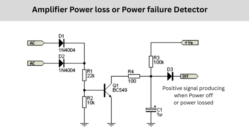
This circuit is designed to detect, when power to an amplifier is lost and to generate a signal immediately when that happens. Such a fast responding power detector is useful in audio systems to prevent unwanted noise or “pop” sounds that occur when power is suddenly switched off or to disconnect relays quickly to protect connected speakers.
Circuit Explanation and Working Principle
The circuit operates by monitoring an unsmoothed rectified voltage derived directly from the transformer’s secondary winding. Two diodes of D1 and D2 which is 1N4004. This half wave rectifier that converts the AC voltage into a pulsating DC. Because this voltage is not filtered by a capacitor, it stops almost instantly when the AC supply is removed. This makes it ideal for detecting the power loss quickly. unlike the DC supply, which may take several seconds to fall due to large filter capacitors.
The rectified voltage is then fed through a voltage divider made up of resistor R1 of 22kΩ and resistor R2 of 10kΩ, which biases the base of the transistor Q1of BC549. As long as the AC power is present, The Q1 transistor remains switched on and keeping its collector near ground potential. In this condition, the output of the circuit remains low, indicating that power is available from the transformer.
When the AC power is turned off, the rectified voltage immediately drops to zero and which will removing the transistors base drive voltage. The transistor then switches off and its collector voltage rises through the resistor R3 of 100kΩ to the positive supply. This sudden voltage rise charges the capacitor C1 (1µF), and it creating a short positive pulse at the output through diode D3. This pulse can be used to trigger a relay, mute an amplifier or signal a microcontroller that power has been lost.
The timing of the output pulse is depending on the values of resistor R3 and capacitor C1. In this design, the delay is approximately 50 milliseconds so this is fast enough to react before large filter capacitors of the amplifier board is discharge. This timing can be adjusted by changing the capacitor values by increasing C1 extends the delay and decreasing it results in a faster response.
This circuit provides a simple and highly effective way to detect power failure instantly. By using the rectified but unsmoothed AC voltage as its sensing source, it ensures immediate reaction when power is removed, making it perfect for protecting sensitive audio or electronic systems.