Doing DJ parties or any wedding programs you need a high power audio system to play sound. Small home audio systems has the limitations, it can only deliver maximum RMS of 100 watt. So You want more power audio amplifier? here I am giving the 300 watt amplifier circuit and connection details along with the components list. You can build this circuit very easy with this guide.
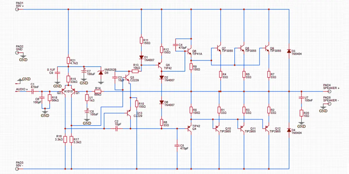
300 Watt Amplifier Circuit Diagram

Connections and Working
The given circuit diagram is representing the 300 watt power amplifier circuit and this is designed in Class AB push pull configuration. The TIP3055 and TIP2955 complementary pair of NPN and PNP transistors are used as the power stage. 50V dual power supply is enough for this amplifier circuit.
The audio input is given through the capacitor C1 and reaches to the base of A1015 transistor. This transistor acts as a pre amplifier. The transistor C2229 is acting as a voltage amplifier. The TIP41 and TIP42 act as the driver stage transistor to drive the power transistors. The power stage is built with three pairs of complementary transistors of TIP3055 and TIP2955.
The Diodes D1, D2, and D6 provide biasing to prevent crossover distortion and capacitor C4 and C5 help maintain stability by compensating for high frequency oscillations. The diodes D3 and D4 protect against back EMF from the speaker. This amplifier circuit is a well balanced driver stage and output stage. It also has appropriate DC biasing, coupling, and decoupling components to maintain linearity and prevent distortion or instability.
Components Required
The components required to build this amplifier circuit is given below, you can purchase this components based on its values.
| Component | Reference | Value / Part Number | Quantity |
|---|---|---|---|
| Resistors | R1-R7 | 0.33Ω / 5W | 7 |
| R8, R9 | 100Ω | 2 | |
| R10, R11, R12 | 150Ω | 3 | |
| R13 | 10kΩ | 1 | |
| R14 | 680Ω | 1 | |
| R15 | 3.3kΩ | 1 | |
| R16, R17 | 3.3kΩ | 2 | |
| R18 | 56kΩ | 1 | |
| R20 | 100Ω | 1 | |
| R21 | 4.7kΩ | 1 | |
| Capacitors | C1 | 470nF | 1 |
| C2, C3 | 10pF | 2 | |
| C4, C5 | 470pF | 2 | |
| C7, C8 | 100µF / 50V | 2 | |
| C9 | 0.1µF | 1 | |
| C10 (U7) | 100nF | 1 | |
| Transistors | Q1, Q2 | A1015 (PNP) | 1 |
| Q3, Q13 | C2229 (NPN) | 2 | |
| Q4, Q5 | TIP42 (PNP) | 2 | |
| Q6 | TIP41A (NPN) | 1 | |
| Q7, Q8, Q9 | TIP3055 (NPN) | 3 | |
| Q10, Q11 | TIP2955 (PNP) | 3 | |
| Diodes | D1, D2, D6 | 1N4007 | 3 |
| D3, D4 | 1N5404 | 2 | |
| D5 | 1N5252B (Zener 24V) | 1 | |
| Connectors | PAD1, PAD3 | +50V, -50V Power Inputs | 2 |
| PAD2 | GND | 1 | |
| PAD4, PAD5 | Speaker Output (+, -) | 2 |