4 x 45 quad bridge car audio amplifier
The Tda7388 is a Class AB power audio amplifier ic. The packaging in the flex watt 25 and it has to be designed for the High end car stereo amplifier application. It consist of fully complementary PNP and NPN configuration. It also allows the rail to rail output voltage swing, so you don’t want to apply the bootstraps capacitors.
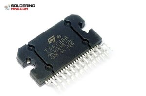
The amplifier ic circuit consist of inbuilt 4 channel audio amplifiers. The IC having high output power capability. The power watts at RMS per each channel of the amplifier delivers 45 w at maximum of 4 ohms.
The optimum configuration of the circuit is 4 x 26w / 4 Ohm @ 14.4 v , 1kHz. The audio amplifier circuit having more features.
Features
- Low distortion
- Providing low output noise.
- Having the standby function.
- Having the feature of Auto mute at minimum supply voltage detection.
Protection
- Great output protection in short circuit to the ground and voltage supply across the load you are connected.
- It having very inductive load.
- Providing Overrating chip temperature, with soft thermal limiter.
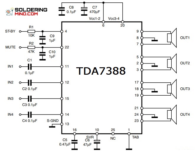
TDA7388 circuit diagram
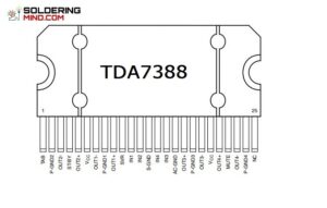
TDA7388 ic pinout
- SG 3525 PWM ic based Power Inverter – Circuit and PCBThe sg 3525 ic is a PWM producing ic. That could be available in all electronics shops with the cheapest price. The ic will cost you around 70 Rupees in the Indian market. check the Sg 35 25 pinouts here. it a 16 pin package and the ic it having the automatic shutdown and soft… Read more: SG 3525 PWM ic based Power Inverter – Circuit and PCB
- TDA2030 Bridged Subwoofer amplifier circuitSubwoofer amplifier – The single ic can produce only the maximum power of 20 watts. in this case, we are bridging two ic and get a maximum power output of 40 watts. it’s good for working a subwoofer with a fine sound. In this, I am going to discuss details about how to make a… Read more: TDA2030 Bridged Subwoofer amplifier circuit
- Current limiting resistor: Glow LED from 230v ACcurrent limiting resistor for Glowing led from ac: The LED (light emitting diode) the LED operating voltage is very low. The working voltage is in between 1.5 to 3v dc. generally, we have seen that there are all indicators in our house on the wall switchboard Are of the neon bulb. which is small in… Read more: Current limiting resistor: Glow LED from 230v AC
- 1000 watts audio amplifier circuit1000 watts audio amplifier circuit using TTA 1943 and TTC 5200 transistor. These transistors are very popular in an audio amplifier. Here is the circuit of 1000 watts in this circuit we can use 10 transistors that means 5 number of TTC 5200 and 5 numbers of TTA 1943 transistor. We know that the words… Read more: 1000 watts audio amplifier circuit
- Subwoofer Amplifier and SubwooferSubwoofer? What is mean by sub? how does the subwoofer work? know detailed about sub-woofer and sub-woofer amp This is the simple questions arise from your mind. when you have seen a sub-woofer. The sub-woofer is alternatively known as sub or woofer. The sub-woofer is a category of a speaker. That designed to reproduce the… Read more: Subwoofer Amplifier and Subwoofer
- LM386 IC Audio Amplifier CircuitLM386 ic Audio amplifier circuit diagram and it’s working. Here we are going to discuss the simple amplifier based on the IC of LM 386. the popular amplifier of LM386 works with 8 ohms speaker. With a few components, you can easily assemble a super amplifier using the lm386 IC. The circuit consists of 1… Read more: LM386 IC Audio Amplifier Circuit
- Amplifier Circuit – 50 Watts Amplifier Using TDA2030Amplifier circuit using Tda2030 and Tda2050. A single TDA2030 IC can deliver up to 15 watts output. We can alter the circuit diagram then we will get up to 50 watts output. to boost up the power of the amplifier we need to introduce two transistors in the circuit. The circuit employs only a few… Read more: Amplifier Circuit – 50 Watts Amplifier Using TDA2030
- Low pass filter circuit for subwoofer amplifier.Low pass filter circuit using NE5532 opamp: The subwoofer amplifier needs a filter board to drive the low-frequency output. The board is specially designed to restrict the high frequency and allowing the low-frequency signals. The subwoofer working frequency is in between 50 hertz to 150 hertz. To get low frequency, it’s specially designing a low… Read more: Low pass filter circuit for subwoofer amplifier.
- 3.7 v li-ion battery charger circuit using lm3583.7 v li-ion battery charger circuit using lm358. it’s a simple circuit that will effectively charge your Li-ion batteries. contain 3 LEDs and that will indicating power on off, charging indicator, and full charging indicator. 3.7 v li-ion battery charger circuit Diagram Working of li-ion batteries The concept of the lithium-ion battery was initially conceived… Read more: 3.7 v li-ion battery charger circuit using lm358
- Automatic Lead-acid Battery Charger – 12v 5a battery chargerAutomatic Lead acid battery charger – This is a very simple and effective circuit for charging the batteries. with a low-cost project, you can control the charging of the 12v battery. The circuit mainly composed of 555 timer ic. The timer IC that cut off the relay and stop charging when the battery charge is… Read more: Automatic Lead-acid Battery Charger – 12v 5a battery charger

