This 2SC5200 amplifier circuit provides the maximum power output of 50watts at 4 ohms impedance. A complementary pair of transistors are using in this circuit. 2SC 5200 and 2SA 1943 is complementary transistors which are mostly using for power audio amplifier building. Because of the voltage range and low noise productions. so the transistors are using in power audio amplifier circuits. These are NPN and PNP power transistors.
Circuit Diagram
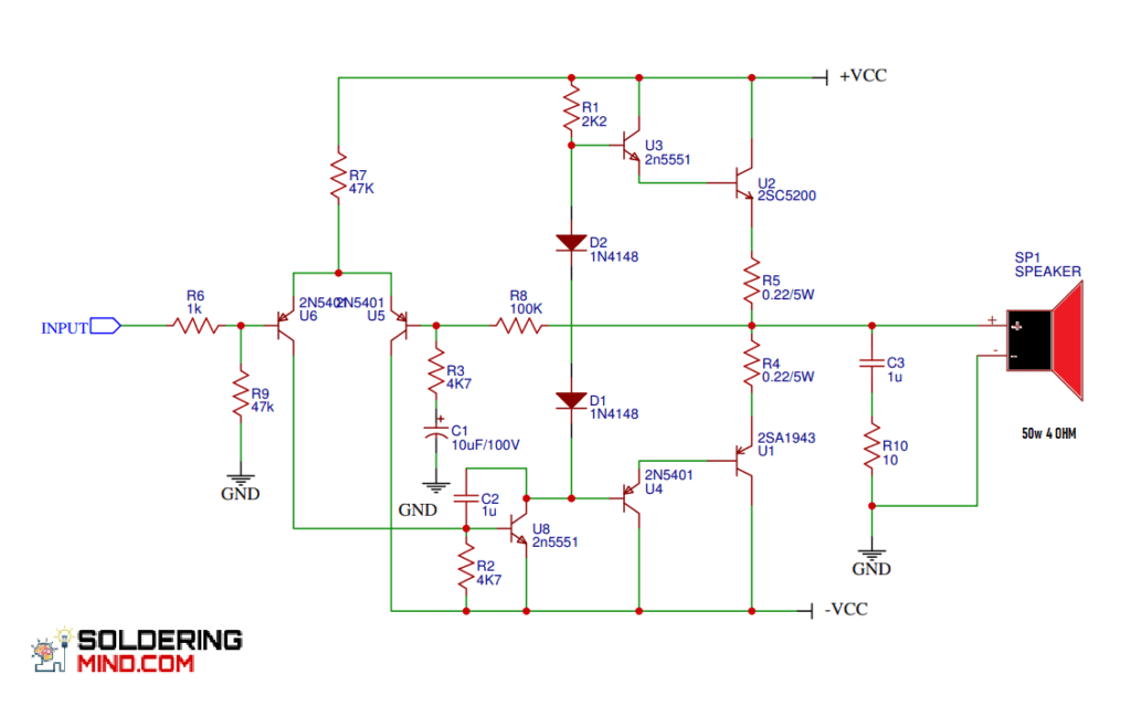
A single complementary transistors can produce about 50 watts 100 watts. The circuit is design as a mono audio amplifier. If you want to build a stereo audio amplifier unit 2 to build to separate mono amplifier board. Low cost audio amplifier circuit we can build at your home the free PCB layout and the PCB silkscreen is given below the website you can easily download through the link.
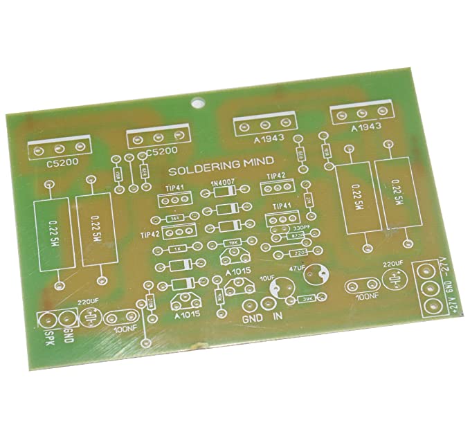
2SC5200 2SA1943 PCB
Ready made PCB to build your own Amplifier. 300 watt max RMS output,suitable for Subwoofer and stereo audio amps.
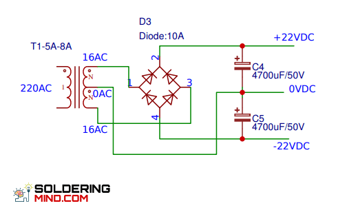
Power supply
For providing the power supply to the audio amplifier we need to take a a 528 ampere transformer and 16 volt with the centre tap. For the rectification purpose we need to add diode from 10 ampere. Use two 4700uf capacitors for the filtration. How filtering capacitor is adding upto 10000 microfarad it will reduce the noise producing in the audio amplifier.
Usse good quality heat Sink on the the transistors because large amount of heat producing by the transistors when it worked the maximum level. And the proper grounding should be e confirmed because the failure in grounding to the cabin will leads to the invoice generation when playing the music.
Transistor pinout
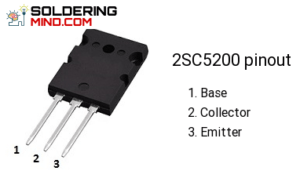
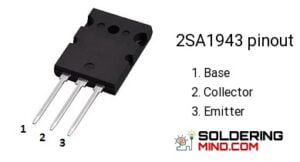
- NPN and PNP transistor
- Complementary pair of the transistor from Toshiba
- High power carrying capacity
- collector-emitter voltage is 230v
- collector to base voltage is 230v
- Control low frequency to high-frequency audio signals easily.

Mine playing with a dirty sound. Voltage 22-0-22
Check driver stage and components
Please send your YouTube link..
Circuit is working well.. Thankyou
i build this schematic circuit but no sound i am not sure wath is GND wath you connect there ? is 0 V reference?Thanks
Perfectly working circuit check our youtube channel
i can’t find it on youtube chanel
YouTube channel name: Life of electronics
It really works and sound is great
Thanks for your genuine comments
Does it support 45vdc-0-45vdc PSU?
Max voltage is 35-0-35
Does it support 45vdc-0-45vdc PSU?
I have built it and was sounding really good.
Thanks for the valuable comments
Mine playing with a dirty sound.. cracking sound… 22-0-22
I am not able to simulate this circuit. Is it a working circuit ?
Do I have to use 2n5401
No
I have tried to simulate this circuit, but it will not work. Have you tried it in real life ?