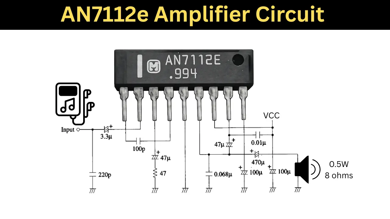
The AN7112e is developed by Panasonic. This IC is use as small audio amplifier which wives0.5Watt at 8 ohms speaker. This IC based Amplifier circuit is using in battery powered electronic devices like mini ratio, pocket FM and recorders. This article shares AN7112e amplifier IC wiring diagram and details.
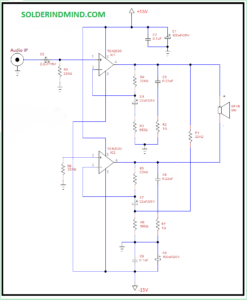
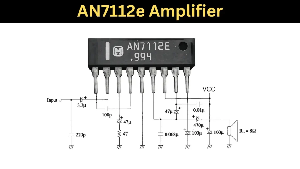
AN7112e Circuit Diagram
AN7112e Pinout and Pin Description
| Pin No. | Pin Name | Description |
|---|---|---|
| 1 | Phase Compensation | Frequency stability capacitor connection |
| 2 | Input | Audio signal input |
| 3 | N.F.B. | Negative feedback input |
| 4 | Phase Compensation | Additional compensation pin |
| 5 | GND | Ground |
| 6 | Output | Audio output to speaker |
| 7 | VCC | Supply voltage |
| 8 | Bootstrap | Bootstrap capacitor connection |
| 9 | Ripple Filter | Power supply ripple rejection |
Components Required
| Sl. No | Component | Value | Quantity |
|---|---|---|---|
| 1 | IC | AN7112E | 1 |
| 2 | Capacitor (Electrolytic) | 3.3 µF | 1 |
| 3 | Capacitor (Ceramic) | 220 pF | 1 |
| 4 | Capacitor (Ceramic) | 100 pF | 1 |
| 5 | Capacitor (Electrolytic) | 47 µF | 2 |
| 6 | Capacitor (Electrolytic) | 470 µF | 1 |
| 7 | Capacitor (Electrolytic) | 100 µF | 2 |
| 8 | Capacitor (Ceramic) | 0.068 µF | 1 |
| 9 | Capacitor (Ceramic) | 0.01 µF | 1 |
| 10 | Resistor | 47 Ω | 1 |
| 11 | Speaker | 8 Ω | 1 |
| 12 | Power Supply | 4V to 14V DC | 1 |
Wiring Connections and Working
This amplifier circuit working in 4 to 14V DC supply. I recommend to give 6V DC supply for 0.5Watt output at 8 ohms speaker. The pin 3 is connected to a 3.3uf electrolytic capacitor and this connection is used as the audio input to the IC.
The Pin number 4 is connected using a 100pf ceramic capacitor, this pins are phase compensation pins. this is frequency stability capacitor. The pin 6 from the IC is the audio output pin and a 470uf electrolytic capacitor is using to filter the DC voltage from the audio out.
Applications
- Radio Amplifier.
- Mini MP3 Player.
- Audio Recording device.