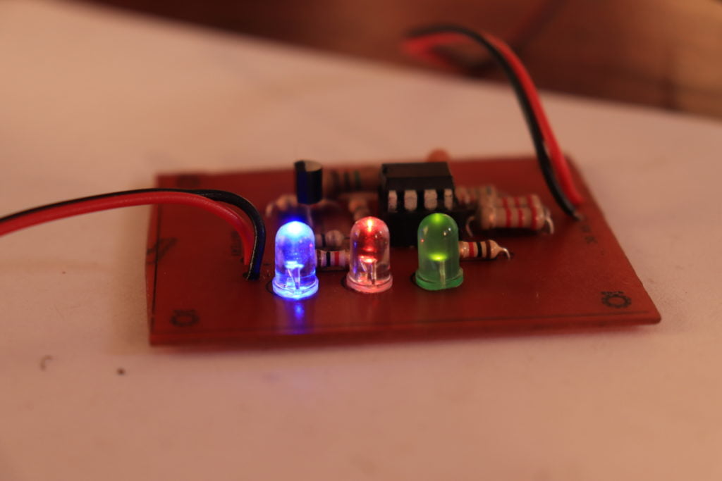
3.7 v li-ion battery charger circuit using lm358. it’s a simple circuit that will effectively charge your Li-ion batteries. contain 3 LEDs and that will indicating power on off, charging indicator, and full charging indicator.
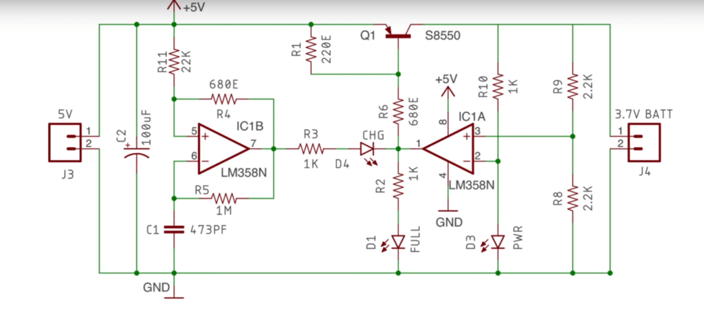
Circuit Diagram
Working of li-ion batteries
The concept of the lithium-ion battery was initially conceived in 1970 and begin to see widespread adoption by 1990. Old lithium-ion cells are deep cycle meaning that they have the ability to be fully charged and discharge.
The life of the battery will significantly increase if the depth of each discharge is limited to 80 percent of the rated capacity.
Life Cycle and Performance
Lithium-ion batteries have significantly higher life cycle than lead-acid batteries. in deep discharge application, the disparity is further increased ambient temperature increase. The cycles life of each chemistry can be increased by limiting the depth of discharge rate, and temperature, but lead acid is generally much more sensitive to each of the factor.
In hot climates, where the average temperature is 83 degree Celsius. the disparity between lithium ion and lead acid is further exacerbated. The cycles life of lead-acid drops to 50 percentage office moderate climate rating while lithium-ion will remain stable handle temperature routinely exceeds 49 degree Celsius.
Advantages and Limitation of Lead-acid Batteries
Advantages
- Inexpensive and simple to manufacture in terms of Cost per watt-hour. the SLA is the least expensive
- mature reliable and well-understood technology. used correctly SLA is durable and provide dependable service
- low self-discharge, the self-discharge rate is among the lowest in the rechargeable battery system.
- Low maintenance requirements. no memory no electrolyte to fill capable of high discharge rates.
Limitations
- The battery Can’t stored in a discharge condition.
- low energy density for weight to energy density limits used to the stationary and wheeled application.
- Allow only a limited number of full discharge cycle well suited for standby applications that require only occasional deep discharge.
- Thermal runaway can cure with improper charging.

I want the voltage to go from 3.7 to 4.2. What changes should I make?
you need to adjust some resistors values
which ones ?
Great, now you don’t reply to my reply.
Bottom line, this circuit doesn’t work, like all the rest made by Indians.
Circuit is working fine check our youtube channel
Hi,
I have made this circuit for the 4th time and still not working, with new components.
This time, RED led OFF, GREEN and BLUE LEDs ON.
In the video, you start by assembly a polyester capacitor but in the test you have a ceramic capacitor.
I have tested with both and still not working.
Actually the given circuit is working perfectly. You need to calibrate the circuit then only it will start to work.
473pf doesn’t exist. 473 is 47nF
473 ceramic capacitor and polyester are available
I think this circuit doesn’t work.
It is working project my friend
Hi, I have assembled this circuit, but the RED LED is not blinking. It’s always on. The charging voltage has reached 4.6V and it’s still charging.
At which voltage does the circuit shuts off?
The green LED doesn’t turn on and red off.
What is going on?
Check the youtube video demonstration
there is’nt capacitor 2 and resistor 7 are not according to diagram, and why did you put the ceramic disc capacitor instead red capacitor (470pf) in the video? please solve my doubts that I am very excited about this project
What is 473pF???? 473k is 47nF not some weird 473pF
how many call can peral in charge
Great job! I made this project yesterday and worked just fine.
Thanks for sharing
THANKS