Introduction
The simple NiCd battery charger circuit is designed to charge the battery with high efficiency. The nicad batteries are a different type of battery from the others like lead acid and lithium ion batteries. The nicad battery consists of nickel oxide hydroxide and the electrode of metallic cadmium.
These batteries are able to provide high current so we can use these batteries in various applications like, power supplies, Power tools like drill, or other power required electronic devices.
So in this article I would like to share the detailed idea about how you can charge the nicad batteries using external power sources like solar panels or transformers. The circuit diagram and the working principle of the circuit is explained here.
Circuit Diagram
Components Required
| Component | Designator | Value | Quantity |
|---|---|---|---|
| Transistor | Q1,Q2 | 2N2222A | 2 |
| Diode | D1, D2 | Bzx55c, 1N4007 | 1, 1 |
| Resistor | R1,R2,R3 | 1K, 10ohms, 2K | 1,1,1 |
| LED | D3, D4 | – | 1, 1 |
| capacitor | C | 100uf | 1 |
Working
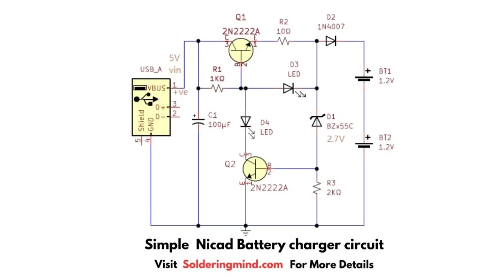
A 5V from the USB is given as the power source, you can use either a transformer or a solar panel to provide the power to this circuit. The initial capacitor C1 acts like the filter capacitor to filter the input DC voltage.
The transistor Q1 acts like the current limiting element. The transistor can provide up-to 120mA of current at the output section of it. The two LEDs are present in this circuit. The D3 acts as the indicator for the charging of the battery. The D4 is for the battery full charge indication.
The zener diode of BZx55c regulates the voltage to 2.7v. When the battery reaches full charge, the Q2 transistor turns on and the LED D4 turns on, at the same time the transistor Q1 stops working. You can change the full charge sensitivity and change the R3 to a variable resistor.