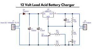
12v lead acid battery Best automatic battery charger. in this article, I’m going to explain the low-cost battery charger circuit and free PCB layout. The circuit is working based on a single transistor of C1815 and a common relay of 12v 10a. The cut-off circuit contains small electronic components. After constructing this circuit adjust the 10k pot ( from 13v to 15 v ).
Then connect the charger on the circuit, when the battery charged fully. The circuit will be turned on and cut off the connection. on charging the LED will be turned on . when the charge reaches about 14v the relay will cut off and the battery full the led will be turned on.
12v Automatic battery charger circuit
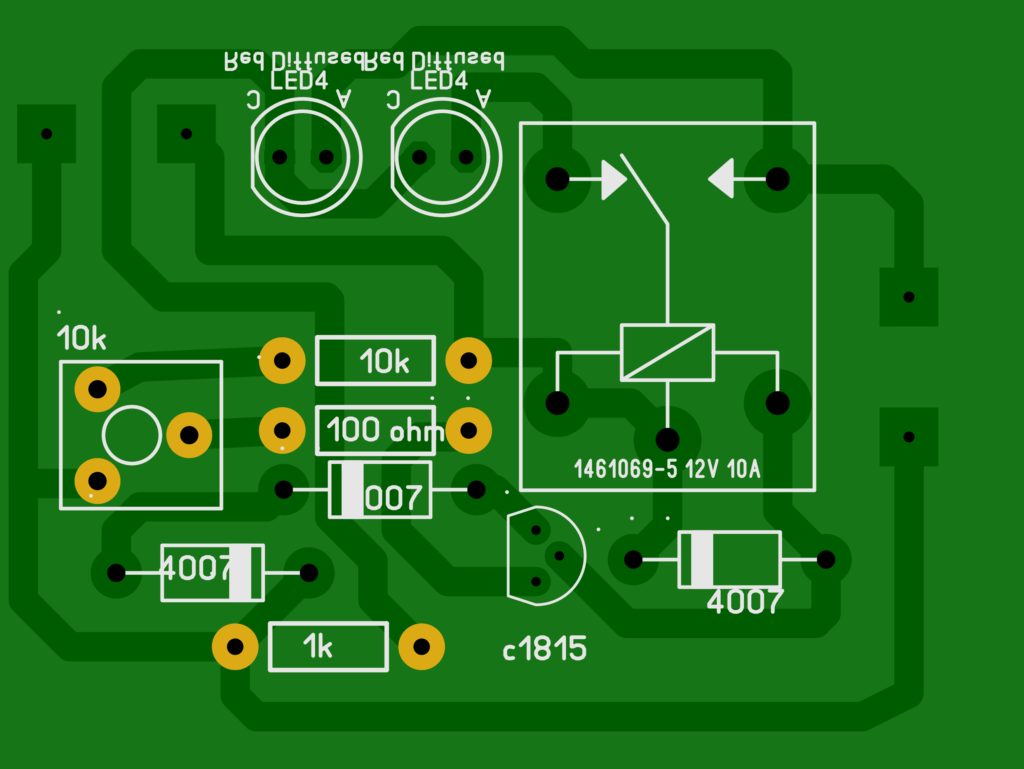
Components Required
- c1815 transistor———————————————1
- 12v 10a relay————————————————-1
- 10k pot———————————————————–1
- 1N4007 diode ————————————————-3
- 10k resistor—————————————————–1
- 100 ohm resistor———————————————1
- 1k resistor——————————————————1
- LED —————————————————————-2
Working
The automatic cut off circuit working based on the increased voltage while charging the battery. when the battery get fully charged the charger rises the voltage from 13-14v, and that voltage has to be detected by the transistor c1815 and turned off the charging process.
we can adjust the cutoff voltage limit by tuning the 10k potentiometer on the board. the battery gets fully charged the positive volt rushes to the transistors positive terminal and turned on, and stop charging.


10 pcss