Lithium ion batteries are the most common nowadays. The compact size and high power current carrying capacity of these batteries are important. So in this post, i would like to share the Li ion Battery charge Balance Circuit using HY2213 IC.
The process of charging lithium ion batteries is like the dancing of lithium ions between the positive and negative ends of the battery. So, protecting the battery from overcharging is important.
The lithium ion batteries consist of two ends such as the Negative side ( Anode ) and the positive side ( cathode). The anode is made up of graphites.
The cathode is using lithium metal oxide. By the help of the electrolyte inside the battery moves the lithium ions from anode to cathode.
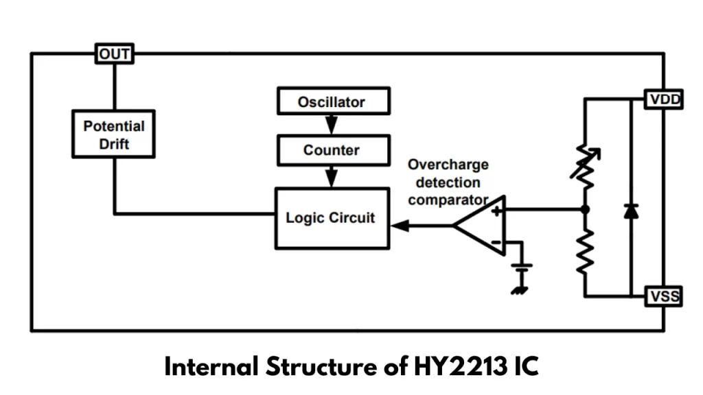
Internal Structure of HY2213 IC
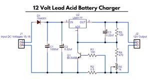
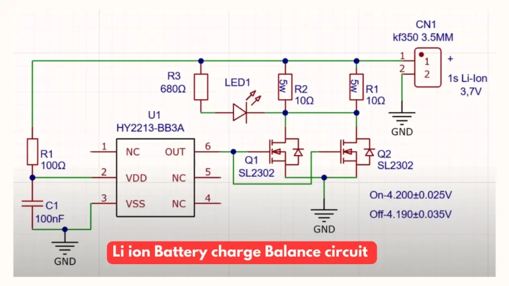
Circuit Diagram
Description
The HY2213 IC is designed to convert the multicell battery pack to the single cell li ion battery charge balance control. This acts like the electrical level monitoring and high accurate voltage detection circuit.
Features of this IC
- Overcharge detection voltage 4.000 ~ 4.500V
- Overcharge release voltage 3.800 ~ 4.500V
- Standby detection voltage 2.70V
- Standby release voltage 2.70V
The Delay time is generated by the internal circuit of the IC. The IC comes with small packaging as SOT-23-6. The main application of this circuit is multi cell Li ion rechargeable battery pack.
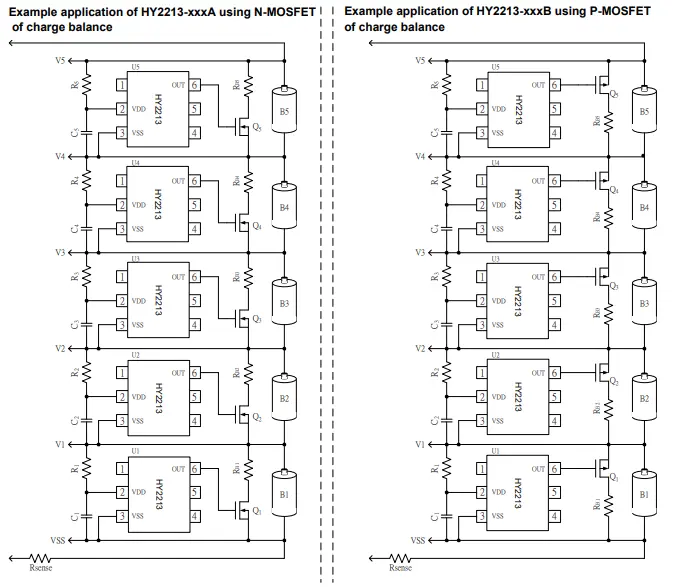
Multicell Li ion Battery Charge Balance Circuit
You will Also Like this
- Simple Lithium Ion Battery Charger Circuit using TP4056 IC
- Simple NiCd Battery Charger Circuit
- Battery Charging Time Calculator