This Ac Motor speed controller circuit is working based on the Triac and Diac. You can use household equipment like a drilling machine to control the rotating speed of it.
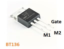
BT136 Pinout
The speed of the electric motor adjusted by rotating the preset pot on the board. Rotate the preset pot to left side right side to increase the speed and left to decrease the speed.
- Also, check Ac motor speed control circuit
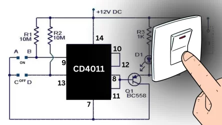
Circuit Schematic
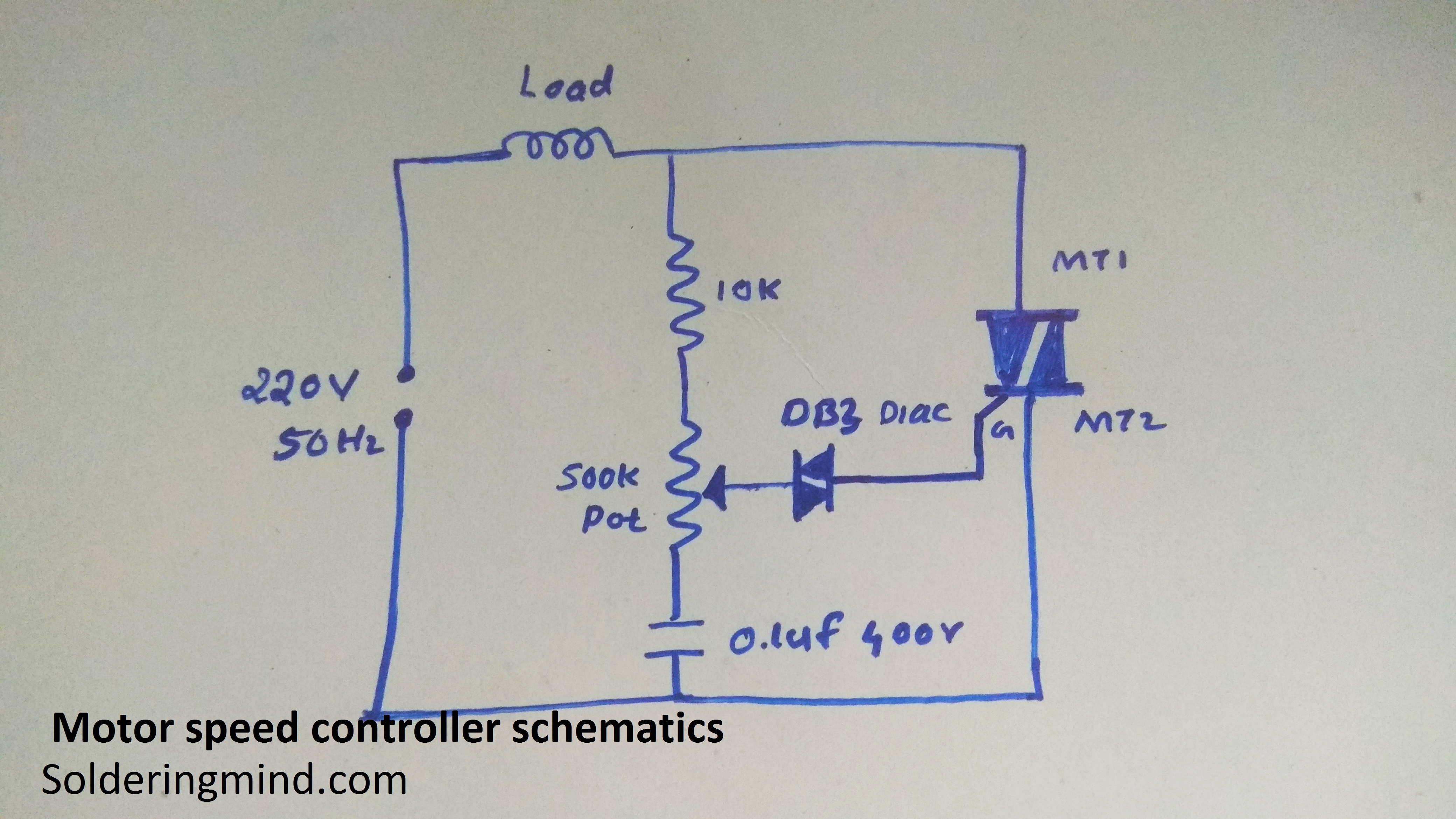
This motor speed control circuit diagram contains a few components such:
- BT136 Triac
- DB3 diac
- 0.1 uf 400v capacitor
- 500k pot
- 10k resistor
- Ac input and output connector
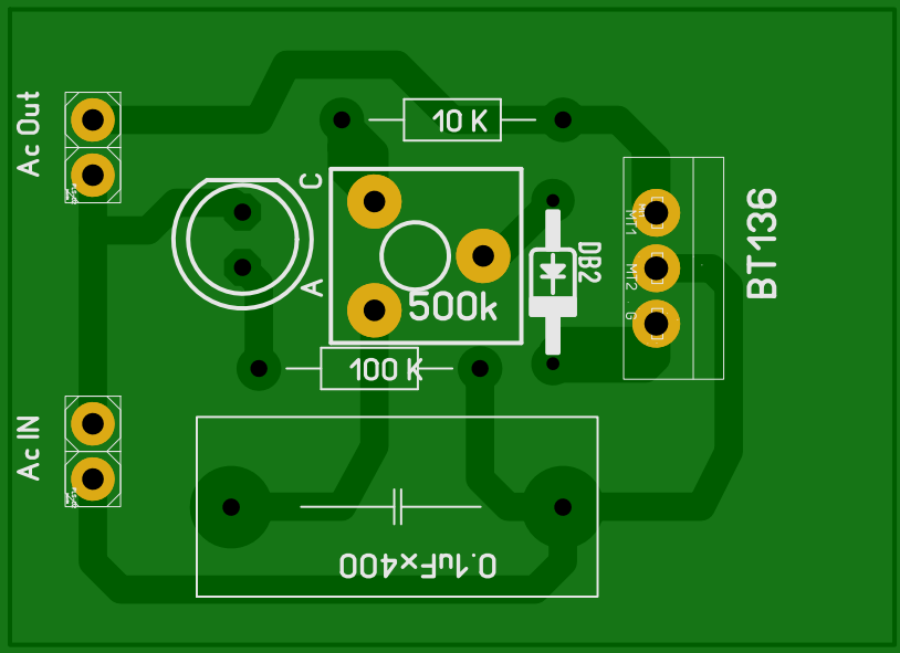
The motor speed control board is also included in this article. you can able to access this free PCB layout without any cost.
PCB Layout
Working of AC motor controller
This circuit is working based on the triac of Bt 136. It has the maximum terminal current is 4A. so you can only use up to 800 watts of electric equipment to control it.
A proper heat sink must be fitted with Bt136 triac. Because the heat should be produced during the working of the motor controller.
Adjusting the preset pot will regulate the input voltage to the triac. so the triac will allow the AC voltage in a controlled manner. This is the main principle of this circuit.

This didn’t work for me.
It looked fine with a bulb, but the triac failed short circuit the first time I connected a 400W motor.