Constructing a Vu meter ( volume unit meter ) is simple. The LM3915 will provide the functions to building a simple VU meter at home. the lm3915 Vu meter circuit is designed with few components. in this article, I am going to share some ideas about the simple VU meter by using lm3915 ic. construction of Vu meter is simplified by the PCB layout. in my own effort, I designed a PCB layout for this circuit.
Working
The working of the Vu meter is very easy to understand, this Vu meter is working based on the ic of LM3915.
Which is an 18 pin led driver ic, is well developed by the company and working with the range of 30dB. Many simple circuits are available on the internet related to the audio led visualizer. Which is most important in audio systems to find out the DB of the sound. majority of the peoples building this circuit for self-satisfaction.
The transistor Vu meter is available but it having some complicated circuits, and also need more components to build those circuits. The circuit is working by an input audio signal has to be injected to the lm3915 ic. then it will process the frequency of the audio signals and switch specific driver transistor ( inside the ic chip ) and turn on the output stage.

The connected 10 led on the output pins of the ic will be turned on and off according to the audio input frequency.
Why the audio level display is needs?
In many application such as power amplifier, DJ system, and small audio systems and audio mixer needs these kinds of the audio display to measure the level of audio signals. and also using the audio level meter you can identify the level of volume and also the noise on the amplifier.
The sound Vu meter or audio sound level meter which is available in the home cinema setup or the stage show programs to improve the stage decorations, this also gives a special look for the stage performance. The sound level meter will be working according to the input signals we are giving.
LM3915 as a sound level meter
The circuit will utilize one 18 pin ic and few electronic components. It displaying the sound level as 10 units ( 10 LEDs). The input voltage is in between 12-20v dc supply. the ic will be providing the function of mode selection as dot mode or floating mode.
LM3915 pinout
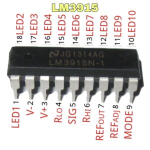
- 1,10 – 18 – output pin for driving 10 LEDs
- 2 – ground pin of the ic ( connecting the negative terminal of the battery )
- 3 – positive supply voltage pin
- 4 – Low-level voltage for potential divider
- 5 – audio or analog signal input pin
- 6 – High-level voltage for potential divider
- 7 – Output reference for led current limit
- 8 – Adjust pin for voltage reference
- 9 – Mode selection pin ( dot or bar audio visualization )
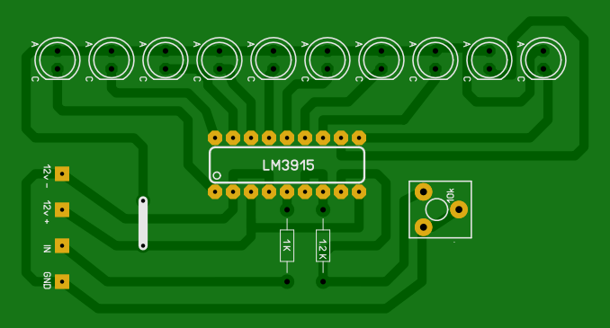
LM3915 VU meter circuit diagram
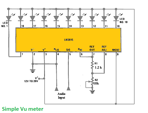
Components required
- Lm3915 ic – 1
- LED – 10
- 1k resistor – 1
- 1.2k resistor – 1
- 10k pot – 1
- jumper wire
In this audio level indicator or sound level meter the Lm3915 ic pi number 1, and 10 to 18 are directly connected to the Led negative terminals. connecting the common positive to the LED. Pin number 4 and pin number 5 are connected to the ground connection.
Pin number 5 is the audio input pin, we can give an audio signal through this pin. NOTE: if you are directly connecting to the output stage of the power amplifier in that time connect a 1k ohm resistor to the 5 the pin connection
A 10 k preset pot that provided on the reference pin. you can adjust and set to the minimum to start showing visualization. Pin number 9 is the Mode selection switch pin that allows you to select the bar mode of led visualization of dot mode, I preferring the bar mode because is very beautiful to see. Download the VU meter PCB layout file to build your own at home.


please guide me how to make a high frequency pre amp with use of 5532 op-amp ic
emty files