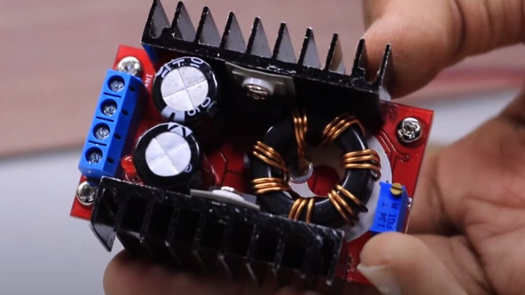
Most of you familiar with this 150w dc to dc boost converter board. The boost converter board can able to provide up to 35V dc in the output (12v to 35v ). So in this article i would like to share the Schematics of this dc to dc boost converter and explaining about how it is working.
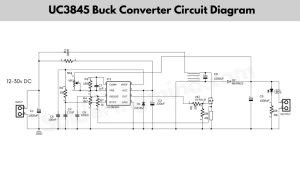
150w DC DC boost converter circuit schematics
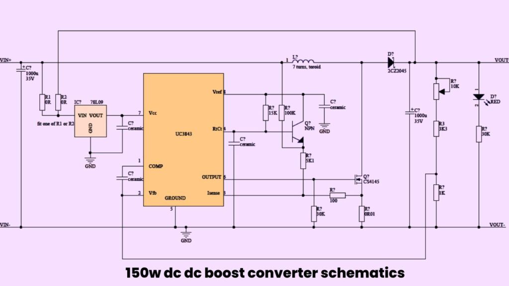
The boost converter is working with UC3843 IC. The input voltage of this circuit is 10v to 35v DC, means if you applied 10v on the input section you can get upto 35v dc with 6A current. More specification of this circuit is listed below.
| Specification | Values |
| Input voltage | 12v to 35v DC |
| Output voltage | 12v to 35v DC ( Adjustable ) |
| Maximum out put current | 6A |
| Maximum Input current | 10A |
| Full load temperature | 45 degree Celsius |
| Working temperature | Upto 85 degree Celsius |
Components required
| Components | quantity needed |
| UC3843 IC | 1 |
| 7809 voltage regulator ic | 1 |
| CS4145 Mosfet | 1 |
| 2sc3142-3 transistor | 1 |
| toroid core with 7 turns | 1 |
| 2cz2045 Diode | 1 |
| 10k pot | 1 |
| 1000uf/35v capacitor | 2 |
| ceramic capacitor pin 1 to 2 | 100nf |
| ceramic capacitor pin 4 to ground | 1.2nf |
| 1k,100 ohms, 15k, 5.1k, 30k, 0.01ohms 5watt, 3k3 resistor | all need 1 -2 pieces |
Working
The UC3843 is a popular IC using in smps circuits. The ic is build with a pulse width modulation circuit to control output voltage of the power supplies.
The internal structure of this IC consist of Oscillator, error amplifier, PWM comparator, Feed back loop circuit.
The oscillator circuit inside of the ic will produce the Sawtooth waveform at a high frequency. The frequency is determined by the externally connected components to the circuit.
The error amplifier will cross check the reference voltage applied through the voltage regulator and output voltage of the power supply. Then it will produce the error signal on it.
The PWM comparator receiving this error signal and it will compare the error signal with the sawtooth wave form.
Depending on this comparison the circuit will turn on and off at a particular cycle. as a switched mode powering. the output signal is taking out from the pin number 3 of the IC to drive the power mosfet.
This is the working of the 150w dc dc boost converter, so you can easily build this circuit at home for bench power supply. if you like this article don’t forget to share on social media.
You may also like
- Power Supply for Audio Amplifier
- Variable voltage power supply
- 30v 10a DC Variable Power Supply Circuit
- Comparison Between TIP35 vs TIP3055