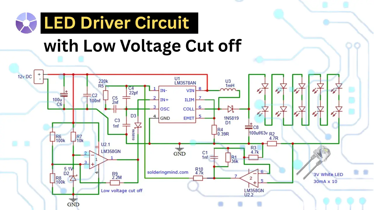
if you are looking for a LED driver circuit with additional features of Low voltage cut off? in this my project i am sharing the simple LED driver circuit for connecting multiple white LED’s. Use a 12V DC power supply to get brighter light using this 10 LED’s. The circuit using a LM3578 IC, which boosting the 12V DC to 37V and driving the series connected LED’s. All connected LED’s must has a 30mA of forward current rating. The LM358 IC will turn of the circuit if battery voltage is below 10V. This project is ideal for DIY lighting projects, portable devices, and energy efficient LED applications.
Components Required
| Component | Value / Part Number | Description |
|---|---|---|
| U1 | LM3578AN | Step-up (boost) converter IC |
| U2.1, U2.2 | LM358GN | Dual Op-Amp IC (used for low voltage cutoff and feedback) |
| Q1 | (Internal to LM3578AN) | Switching transistor |
| D1 | 1N5819 | Schottky diode for boost output |
| D2 | Zener 5.1V | Voltage reference for low voltage detection |
| D3 | 1N5819 | Schottky diode for feedback isolation |
| R1 | 36kΩ | Feedback resistor |
| R2, R3 | 4.7Ω | Current limiting resistors |
| R4 | 0.39Ω | Current sense resistor |
| R5 | 220kΩ | Oscillator resistor (frequency setting) |
| R6, R7 | 100kΩ | Voltage divider for Zener reference |
| R8 | 100kΩ | Zener pull-down resistor |
| R9 | 2.2MΩ | Hysteresis resistor for op-amp |
| R10 | 4.7kΩ | Feedback resistor for op-amp |
| C1 | 1nF | Compensation capacitor |
| C2 | 100nF | Decoupling capacitor |
| C3 | 1nF | Oscillator capacitor |
| C4 | 22pF | Timing capacitor |
| C5 | 2nF | Compensation / timing capacitor |
| C6 | 100µF / 25V | Input filter capacitor |
| C8 | 100µF / 63V | Output filter capacitor |
| L1 (U3) | 1mH | Boost inductor |
| LEDs | 3V White LEDs × 10 | Output LEDs (30mA each) |
| Power Source | 12V DC | Input power supply |
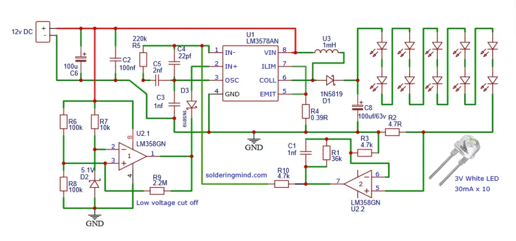
LED Driver Circuit Diagram
How to Wind 1mH Inductor for LED Driver
The inductor is winding using a ferrite round core. The ferrite core with a permeability μr, the number of turns reduces drastically. So the inductance formula is,
Inductance L = N2*μ0*μr*A/2*pi*r
Example Calculation (Assumed Values):
- Outer diameter = 25 mm
- Inner diameter = 15 mm
- Height = 10 mm
- μr = 2000 (typical for ferrite).
By calculating the number of turns using this given formula, around 11 to 12 turns is needed to get 1mH on this example core.
Tips for Building and Testing the Circuit
- You need choose the right inductor and capacitors.
- Ensuring proper heat dissipation for the LED.
- You must verifying the current limit with a multimeter.
- It is your choice to Use a breadboard or PCB for prototyping.
- You need to take sufficient safety precautions when working with higher voltages of up to 37V DC.
How the LED Driver Circuit Works
The 10 white LED are connected in series, So a single LED needs 3V to glow brightly where 10 LED needs 30V DC. This high voltage is providing by the LM3578 DC to DC boost converter IC. This IC is also used in motor speed control and buck converter circuits. The 1mH inductor coil and Schottky diode is used in this circuit to boost the input 12V DC to 37V DC.
The additional low voltage cut off feature is controlled by the LM358 op amp IC. Two 100K resistors are using in the inverting input of op amp IC for the reference voltage. A 5.1V Zener diode is connected to the pin 2 of the op amp IC. This IC configuration is working as a comparator which checking the reference voltage and the current voltage level. When the Voltage going below 10V the IC stops the entire circuit and LED stops glowing.
Advantages of This Boost LED Driver Design
- The circuit is efficient in power conversion from 12V Dc to 37V Dc for LED’s.
- This circuit has the ability to power multiple LEDs in series of upto 10.
- The built in battery protection is providing via low voltage cutoff feature.
- Circuit is simple and compact design using commonly available electronics components.
- It has a stable current regulation for longer LED life.
Applications of This LED Driver Circuit
- 12V Battery powered LED lamps.
- Emergency lighting systems.
- Solar powered lighting setups