This one transistor-based circuit gives a classic fuzz distortion sound and you will like this. The circuit to build only needs a high gain NPN transistor which can be used as MPSA18, BC108 or 2N3904. In my recommendation, use MPSA18 because it has up to 1500 hFe gain value. In this article, I’m sharing the circuit diagram and components list to build your own.
What is Fuzz Effect?
The fuzzy effect is the high clipping distortion produced by the circuit when the input signal is received. The input signal is pushed to high clipping waveforms, producing a buzzing and thick sound in the output. The fuzz effect is achieved by overdriving the high-gain NPN transistor.
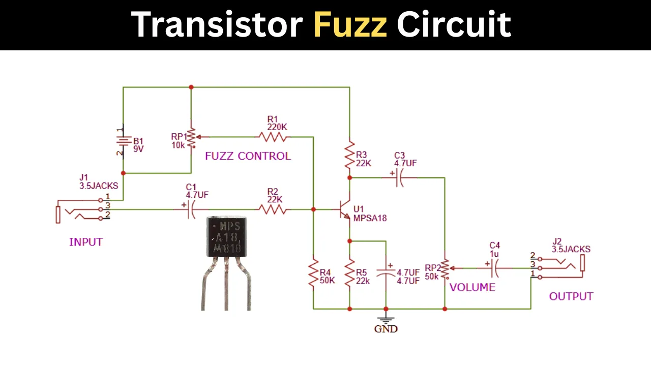
One Transistor Fuzz Circuit using High Gain NPN Transistor
Components Required
- U1 – MPSA18 NPN Transistor ×1
- R1 – 220 kΩ Resistor ×1
- R2 – 22 kΩ Resistor ×1
- R3 – 22 kΩ Resistor ×1
- R4 – 50 kΩ Resistor ×1
- R5 – 22 kΩ Resistor ×1
- C1 – 4.7 µF Electrolytic Capacitor ×1
- C2 – 4.7 µF Electrolytic Capacitor ×1
- C3 – 4.7 µF Electrolytic Capacitor ×1
- C4 – 1 µF Electrolytic Capacitor ×1
- RP1 – 10 kΩ Potentiometer (Fuzz Control) ×1
- RP2 – 50 kΩ Potentiometer (Volume Control) ×1
- J1 – 3.5 mm Audio Input Jack ×1
- J2 – 3.5 mm Audio Output Jack ×1
- B1 – 9V Battery ×1
- 9V Battery Clip ×1
- SPST Power Switch ×1 (optional)
- PCB or Perfboard ×1
- Knobs for potentiometers ×2
- Hookup wires
- Enclosure (optional)
MPSA18 Transistor and its Function
This circuit operates based on the high-gain transistor MPSA18 or other alternatives such as BC108 or BC109. This transistor acts as the main amplification component, where the input signal is received and a high current signal is produced at the output.
Fuzz Control Potentiometer (10k)
The 10K is using to control the output fuzz effect. You can easily adjust the effect the rotating the potentiometer.
How the Fuzz Circuit Works
The circuit is working based on the single transistor. In this circuit the input section is given for the guitar audio input. When guitar plays the signal is enters the input section and it passes through the first 4.7µF coupling capacitor. Then it reaches the transistor base pin through a 22k limiting resistor. The MPSA18 NPN transistor amplifies the signal while the biasing network sets the operating point. As the signal level increases, the transistor will clips the waveform and generates the harmonic rich distortion.
The fuzz potentiometer (RP1) will alters the transistor bias and gain. Then the user can easily control the intensity of the effect by adjusting the 10K pot. The amplified and buzzy, distorted signal is then coupled through another 4.7µF capacitor to the volume control. Finally, the output capacitor removes any remaining DC component before sending the signal to the amplifier.
Features of one Transistor Guitar Fuzz Circuit
- Simple single transistor design.
- Low component count.
- Easy to build on per board or PCB.
- Suitable for 9V battery operation.
- Adjustable fuzz and volume controls.
If you like this single transistor based fuzz circuit, share with your friends also. If you have any doubts contact me buddies..