Protect your electronics circuits and stay alert when any short circuit is happens in your device. This Blown Fuse Indicator Circuit will help you to protect the devices and giving a alert sound and LED indication. This simple circuit design will notifies you with a blinking LED and buzzer when a fuse blows, this makes your devices are safeguarded from further damage.
Components required
| Component | Value / Part Number | Quantity | Description |
|---|---|---|---|
| Voltage Regulator | 7805 | 1 | 5V regulator |
| Transistor | BC547 | 1 | NPN transistor |
| Diode | 1N4148 | 1 | Fast switching diode |
| Capacitor | 0.1 µF | 1 | Ceramic capacitor |
| Resistor R1 | 1kΩ, 1/8W | 1 | Resistor for LED circuit |
| Resistor R2 | 2kΩ, 1/2W | 1 | Load-side resistor |
| Blinking LED (RED) | – | 1 | Red blinking LED |
| Green LED | – | 1 | Green LED (shows fuse is okay) |
| Buzzer | HCM-1206X | 1 | 5V buzzer |
| Fuse | Depends on application | 1 | Protects the output load |
The circuit is Designed to work in input voltage of 5V to 30V DC. it features popular electronic components like the 78L05 voltage regulator, BC547 transistor and 1N4148 diode. Whether you’re a hobbyist or a professional electronics enthusiast, this circuit is a must have addition to your toolkit. Learn how this setup works and how you can easily integrate it into your projects.
Circuit Diagram
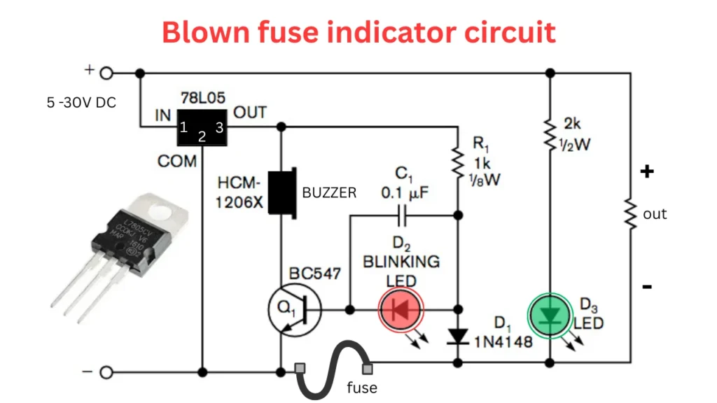
Connection
The blown fuse indicator circuit uses 5 to 30V DC power supply and the 7805 voltage regulator circuit is step down the DC voltage to constant 5V out. This 5V is using for working of buzzer LED and blowm fuse sensing circuit. The regulated output is connected to a 5v buzzer of HCM-1206X and a RED LED (D2) through a 1kΩ resistor and a 0.1µF capacitor. The BC547 NPN transistor is used to control the LED and buzzer operations. The transistors emitter pin is connected to ground and collector connected to the negative load indicator circuit, before the fuse connection.
Working of Circuit
Normal Operation
When the fuse is in normal and good condition the voltage is passing through the fuses and reaches the output section. in this situation Diode D1 1N4148 is in forward biased and the connected green LEd turn on this indicating the fuse is OK. The base of the BC547 transistor remains low, keeping it turned off. As a result, the Red LED and buzzer do not activate.
Blown Fuse Condition
If the fuse blows due to over current or short circuit, the current path to the output is broken. In this case, D1 becomes reverse biased, and D3 (green LED) turns off. Simultaneously, the voltage from the 7805 regulator activates the BC547 transistor through the base, turning it on. This allows current to flow through the blinking LED and the buzzer, alerting the user with both sound and visual signal. The circuit therefore immediately notifies that the fuse is blown and needs replacement.