In market many relay modules are available to buy. Some time they are more convenient to buy this board for quick connections without worries of DIY projects. But I strongly recommending you to stop buying and make your own relay module board using optocoupler IC of PC817.
✅Why Do you Build This?
1. Easy to build and learn about electronics.
2. Understand how it is working practically.
3. Develop skill for PCB making and circuit making.
Relay Module Optocoupler Schematic
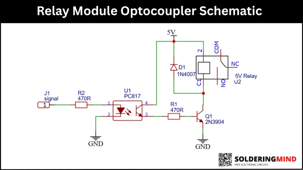
This given schematic uses an optcoupler IC of PC817 to control the relay. This circuit can safely control the high voltage side using a low voltage signal. The signal is coming from the microcontroller IC or Low voltage from a battery. The microcontroller producing only low voltage at its output so, it cannot control a 5V 100mA relay properly.
This circuit is an example of isolation amplifier. The optocoupler provides electrical isolation between the control side and the relay side. This circuit also protecting high voltage sensitive circuits from noise, voltage spikes and damage.
4-Channel Relay Module Board | 5V Relay Module with Optocoupler for boards compatible with Arduino
As an Amazon Associate, I earn from qualifying purchases.
🔥 Check Price on AmazonComponents Used in the Circuit
- PC817 (U1) – Optocoupler for electrical isolation.
- 2N3904 (Q1) – NPN transistor used as a relay driver.
- 1N4007 (D1) – Flyback diode for coil protection.
- R1 (470Ω) – Base resistor for transistor.
- R2 (470Ω) – Current limiting resistor for optocoupler LED.
- 5V Relay (U2) – Electromechanical relay.
- J1 is Input signal pin.
Input Side with Signal and Optocoupler Operation
The input signal from the microcontroller or any low voltage source is connected to the pin J1, The signal is passes through the 470ohms resistor and reaches to the Internal LED connection of PIN1 of optocoupler. Pin 2 of PC817 optocoupler IC is connected to the ground.
When the input signal in applied, that time the LED inside the PC817 optocoupler isturns ON. This light will activates the internal phototransistor. The photo resistor based circuit is completely isolated from the relay side.
Output Side with Transistor and Relay Drive
The phototransistor output pin of the PC817 will operates the base of the 2N3904 NPPN transistor. A 470ohms resistor is used to limiting the over current passing to the transistor.
When the optocoupler conducts, The 2N3904 transistor turns ON. This time the current will flows through the relay coil. When the current passing through the relay will turn on it.
The relay coil need more current so a NPN transistor is used as a switch to boot the current. The
Flyback Diode for Protection
The 1N4007 diode is connected across the relay coil connection. Its purpose is to absorb high voltage spikes generated when the relay coil turns OFF and also protect the transistor from back EMF.
Working Principle of the Entire Circuit
- Input signal is applied to J1 connection.
- PC817 optocoupler internal LED turns ON because of the input supply.
- Light fall on the photo resistor and the Internal phototransistor activates.
- 2N3904 base receives current.
- Transistor saturates and drives relay.
- Relay contacts switch load.
- The diode D1 protects against coil voltage spikes.
Applications
- Arduino and ESP projects.
- Home automation systems.
- IoT control boards.
- Industrial PLC interfaces.
- Motor and pump controllers.
- Smart switch systems.