PC817 is a common optocoupler IC used in various electronic circuits for isolating the signal and supply voltage. This IC internally contains a IR LED and Photo transistor. This article sharing the all needed information’s of Pinout and characteristics.
PC817 optocoupler Pinout

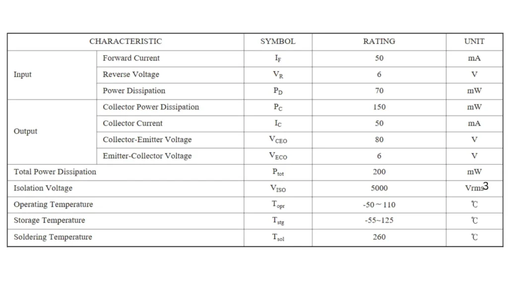
Features and Characteristics of PC817
- PC817 is a 1 channel type optocoupler IC
- Input forward current: 50mA
- Output collector-emitter voltage (Vceo): 35V(Sharp), and 80V for other manufacturer
- Emitter-collector voltage: 6V
- Total power dissipation: 800mW
What is PC817 Optocoupler and Working
The PC817 optocoupler is also known as an optoisolator, it is an electronic component used to transfer the electrical signals between two isolated circuits using light. It consists of an infrared LED on the input side and a phototransistor on the output side, both enclosed inside a single plastic package.
When the current flows through the LED, it emits the infrared light that activates the phototransistor, and allowing the current to pass on the output side transistor. This process gives the signal transmission without direct electrical connection. This will effectively isolating the low voltage control circuit (like a microcontroller) from high voltage or noisy power circuits, so thus will protecting sensitive components.
PC817s are commonly used in switching power supplies, microcontroller interfaces and signal isolation applications. They provide electrical isolation typically rated up to 5,000 volts RMS, with a current transfer ratio (CTR) that determines how much of the input current is reflected as output current.
The CTR and response speed depend on the specific variant and operating conditions. Because of their simplicity, low cost, and reliability the PC817 optocouplers are a staple in industrial control, automation and consumer electronics where safe and noise free signal coupling is essential.
How to Use PC817 Optocoupler IC in a Circuit
To use a PC817 optocoupler, you connect its LED input side to your control circuit and its transistor output side to the circuit you want to control. The input side (pins 1 and 2) works like a regular LED: the anode (pin 1) connects to the control signal through a current-limiting resistor (typically 220 Ω–1 kΩ), and the cathode (pin 2) connects to ground.
When a voltage is applied, current flows through the LED, emitting infrared light inside the chip. This light activates the internal phototransistor on the output side, allowing electrical isolation between the two circuits.
On the output side, the collector (pin 4) of the transistor connects to the target circuit’s voltage through a pull-up resistor (around 4.7 kΩ–10 kΩ), while the emitter (pin 3) goes to ground. When the LED inside the optocoupler is on, the transistor conducts and pulls the output low; when the LED is off, the transistor stops conducting, and the output goes high.
This allows a low-voltage microcontroller (e.g., 5 V Arduino) to safely control high-voltage or noisy loads (like 12 V or 24 V circuits) without any direct electrical connection, protecting sensitive components from voltage spikes or surges.
Safety of PC817 Optocoupler
The PC817 optocoupler is generally very safe when used correctly, because it provides galvanic isolation — meaning the input and output sides have no direct electrical connection. This isolation protects sensitive low-voltage control circuits (like microcontrollers) from high-voltage or noisy circuits (such as power supplies, relays, or motors).
The PC817’s internal design ensures that even if a high voltage spike occurs on the output side, it won’t damage the input circuit, making it a reliable component for signal isolation and noise reduction.
In terms of specifications, the PC817 typically offers an isolation voltage rating of around 5,000 V RMS, meaning it can safely handle large potential differences between its input and output sides. However, its maximum input current (about 50 mA) and output transistor limits (collector current ≈ 50 mA, voltage up to 80 V) must not be exceeded.
For switching large loads or high-speed signals, it’s better suited for logic-level interfacing rather than power control. In short, the PC817 is very safe and dependable for low- and medium-voltage signal isolation, provided it’s used within its electrical ratings and properly protected with resistors.
Applications
- Isolates a microcontroller from high voltage circuits.
- Example: Controlling a relay with a 5V microcontroller while the relay operates at 230V AC.
- Protects sensitive electronics from voltage spikes.
- Prevents ground loops in audio or data transmission circuits.
- Example: Isolating sensors or communication lines to avoid interference.
- Drives high voltage devices like motors through opto-isolated control signals.
- Protects low voltage control circuits from motor voltage spikes.
- Detects zero crossing points in AC circuits.
- Useful in dimmers, AC phase control, and TRIAC triggering circuits.