A zero crossing detector is an essential circuit used in AC signal monitoring and control applications. The given circuit uses an optocoupler IC of 4N35 for safe isolation between the high voltage AC mains and low voltage digital electronics. This circuit effectively identifies the precise moment when the AC waveform crosses zero volts. This is critical for phase control in dimmers circuit and motor speed control and timing applications in microcontroller based systems. The combination of 1N4007 diode and resistors limits current and rectifies the AC signal, while the optocoupler safely interfaces the AC side with a 5V logic output. This generating a sharp digital pulses at each zero crossing.
4N35 Optocoupler Pinout
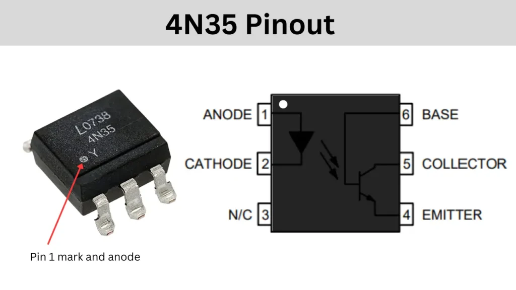
Pinout Configuration
| Pin Number | Name | Description |
|---|---|---|
| 1 | Anode | LED Anode (input side, positive terminal) |
| 2 | Cathode | LED Cathode (input side, negative terminal) |
| 3 | NC | Not Connected (no internal connection) |
| 4 | Emitter | Phototransistor Emitter (output side) |
| 5 | Collector | Phototransistor Collector (output side) |
| 6 | Base | Phototransistor Base (used for external biasing, optional) |
Components Required
| Component | Value / Part Number | Description |
|---|---|---|
| R1 | 56kΩ | Current limiting resistor for AC line (N) |
| R2 | 56kΩ | Current limiting resistor for AC line (P) |
| R3 | 10kΩ | Pull-up resistor for output signal |
| D1, D2, D3, D4 | 1N4007 | Rectifier diode |
| U1 | 4N35 | Optocoupler (transistor output) |
| AC Input | 220V AC | Mains voltage input |
| Output | Digital pulse output | Zero crossing signal (5V logic level) |
| Power Supply | +5V | DC supply for output side of optocoupler |
Zero Crossing Circuit Diagram
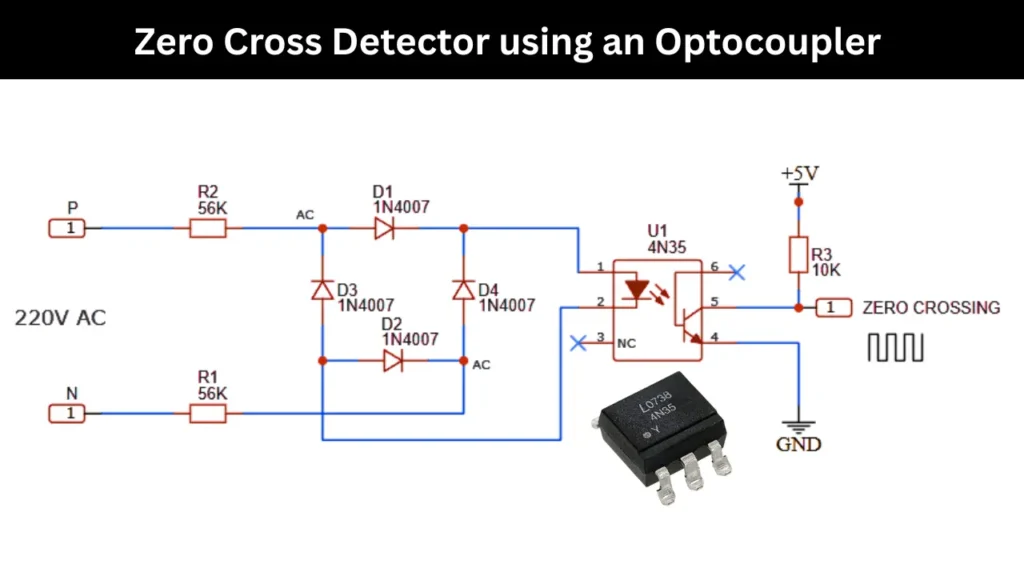
Working Explanation
In this given Zero Cross Detector circuit using 4N35 optocoupler works by sensing the point at which the AC voltage waveform crosses the zero voltage line, this is known as the zero crossing point. The AC input of 220V is passing through Resistor R1 and R2 to limit the current form AC voltage. The limited current is then goes into the Rectifier bridge configuration using four diodes of 1N4007. This arrangement allows the LED inside the optocoupler to turn on whenever the AC voltage is exceeds the forward voltage of the LED, which does not happen near the zero crossing point.
When the AC voltage is close to zero, the LED inside the 4N35 optocoupler turns off and which causing the transistor on the output side to also turn off. As a result, the pull-up resistor R3 brings the output high and generating a digital pulse. These high pulses occur only during the short zero crossing intervals, this creating a narrow and sharp signal each time the AC waveform crosses zero volts. This output can be read by microcontrollers or logic circuits for switching operations in phase control, dimming, and synchronization tasks.
Applications
- AC Power Control
- Motor Speed Control
- Light Dimmers
- Heater Control Systems