This circuit works based on any music detected through the condenser mic and LED get activated based on the rhythm of music. In this article I’m sharing the circuit diagram and working principle of sound activated LED circuit using BC547 and C1815 transistor.
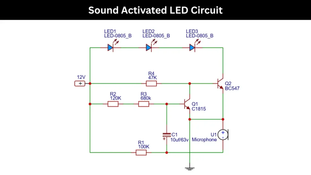
Sound Activated LED Circuit Diagram
Components Required
| Sl. No | Component Name | Value / Specification | Quantity |
|---|---|---|---|
| 1 | LED | LED optional color | 3 |
| 2 | Transistor Q1 | C1815 (NPN) | 1 |
| 3 | Transistor Q2 | BC547 (NPN) | 1 |
| 4 | Resistor R1 | 100KΩ | 1 |
| 5 | Resistor R2 | 120KΩ | 1 |
| 6 | Resistor R3 | 680KΩ | 1 |
| 7 | Resistor R4 | 47KΩ | 1 |
| 8 | Capacitor C1 | 10µF / 63V (Electrolytic) | 1 |
| 9 | Microphone | Condenser Microphone | 1 |
| 10 | Power Supply | 12V DC | 1 |
Circuit Connections
The circuit is working on 12V DC power supply. The positive terminal feeds both the LED section and the transistor biasing circuit. The three LEDs are connected in series and their cathode side is linked to the collector of BC547 transistor.
This acts as a switch for the LEDs. The emitter of Transistor Q2 is connected to ground pin and which will complete the LED current path. The Resistor R4 of 47KΩ is connects from the positive supply to the base of the transistor Q2.
This will help to provide bias and control the switching action. Meanwhile the transistor Q1 of C1815 is connected in such a way that its collector is tied to the base of the transistor Q2. This will allowing it to control transistor Q2 based on the input signal.
On the input side a condenser microphone is used to capture sound signals. One terminal of the microphone is grounded and the other is connected to the emitter of transistor Q1. This will also connect to capacitor C1 of 10µF. This capacitor will filters and stabilizes the signal.
The Resistors R2 of 120KΩ and R3 of 680KΩ form a voltage divider using Resistor series connection and that will provide the required bias voltage to the base of transistor Q1. The resistor R1 of 100KΩ is connects the circuit to ground. This will gives a proper reference and sensitivity control.
When the sound is detected, the microphone produces a small electrical signal that is amplified by the transistor Q1, which in turn drives transistor Q2 and it causing the LEDs to glow based on rhythm.
Working Principle
The working principle of this circuit is based on detecting the sound signals by the condenser mic and amplifying them to drive the LEDs based on the audio rhythm. The connected condenser microphone converts the sound waves into small electrical signals or energy.
The energy is very weak and need amplification. So the Transistor of C1815 is acts as a preamplifier and boosting these signals to a usable level. When a sound is detected, the transistor Q1 conducts and provides a signal to the base of BC547 transistor. This transistor is works as a switching transistor.
As the transistor Q2 turns ON, the current flows through the series connected LEDs, and then it glows. The resistors set the proper biasing and sensitivity. The 10uf capacitor helps to filter the noise and stabilize the signals. This circuit respond smoothly to sound and get sound reactive LED.