The automatic rain sensing wiper circuit is a very simple electronics project and it is designed to automatically activates the vehicle’s wiper motor when rain is detected. This circuit using a DIY rain sensor module, NE555 timer, LM358 operational amplifier, and an L293N motor driver IC.
Components Required
| Component | Specification/Value | Quantity |
|---|---|---|
| NE555 Timer IC | – | 1 |
| LM358 Op-Amp | Dual Operational Amplifier | 1 |
| L293N Motor Driver IC | – | 1 |
| Transistor | BC557C (PNP) | 1 |
| Resistor | 2.2MΩ | 1 |
| Resistor | 10kΩ | 2 |
| Resistor | 1kΩ | 3 |
| Capacitor | 0.01µF | 1 |
| Capacitor | 0.47µF | 1 |
| LED | Red & Green | 2 |
| Rain Sensor Module | – | 1 |
| DC Motor | – | 1 |
| Power Supply | 9V Battery | 1 |
| Connecting Wires | – | As required |
| Breadboard/PCB | – | 1 |
Automatic Rain Sensing Wiper Circuit
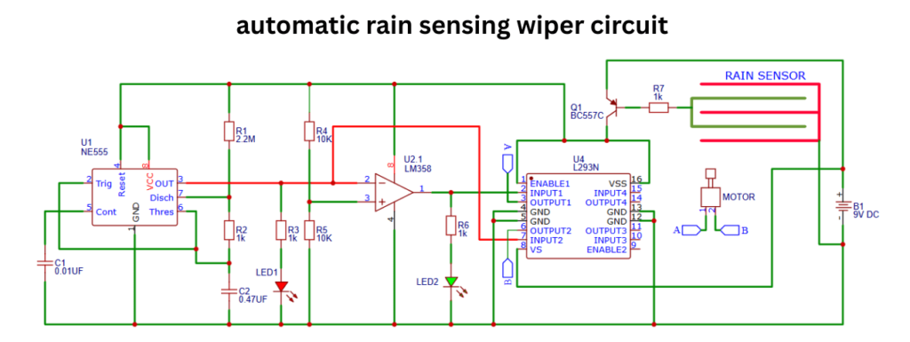
This circuit control the wiper mechanism based on the presence of water in the sensor. This Automatic Wiper System project is great choice for automotive applications and DIY electronics enthusiasts. This smart wiper system gives an improved driver safety and visibility of glasses and no need to manual wiper activation during raining time.
Construction and Working Principle
This given automatic wiper system circuit is build with NE555, Lm358 and L293n motor driver IC. The 555 Ic generating the pulse because it connected in monostable mode. when rain detected The IC start to generate pulse signals. The LM358 op amp is acting as a comparator in this circuit, it will compares the voltage from the rain sensor with a reference voltage. If rain is detected, the sensor resistance changes and it will affecting the voltage at the comparator input. When this voltage drops below the reference value, the op amp output goes high, this will triggering the timer and activating the motor driver.
The L293N is a dual bridge motor driver IC. It will Drives the wiper motor in either directions of front and back. This IC gets the control signals of Input1 and Input2 from the 555 timer IC and LM358 op amp IC. when the signals receives the IC proving the current to the motor for working. The movement direction of the motor is indicating the corresponding LED’s.