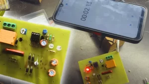
The Arduino based clamp meter is a hobby electronic circuit designed to measure AC current flowing through a conductor without direct contact. Don’t buy an expensive clamp meter to measure the AC current usage. You can easily build and program the circuit. This circuit consists of a few number of electronic components such as Arduino Nano, a current sensor, an LM358 operational amplifier, I2C LCD display, and push buttons for user interaction. So in this article, I will share the circuit diagrams and programming code to build this.
Arduino Based Clamp Meter Circuit Diagram
Components Required
| Component | Quantity | Description |
|---|---|---|
| Arduino Nano | 1 | Microcontroller board for processing data |
| LM358 Op-Amp | 1 | Dual operational amplifier for signal processing |
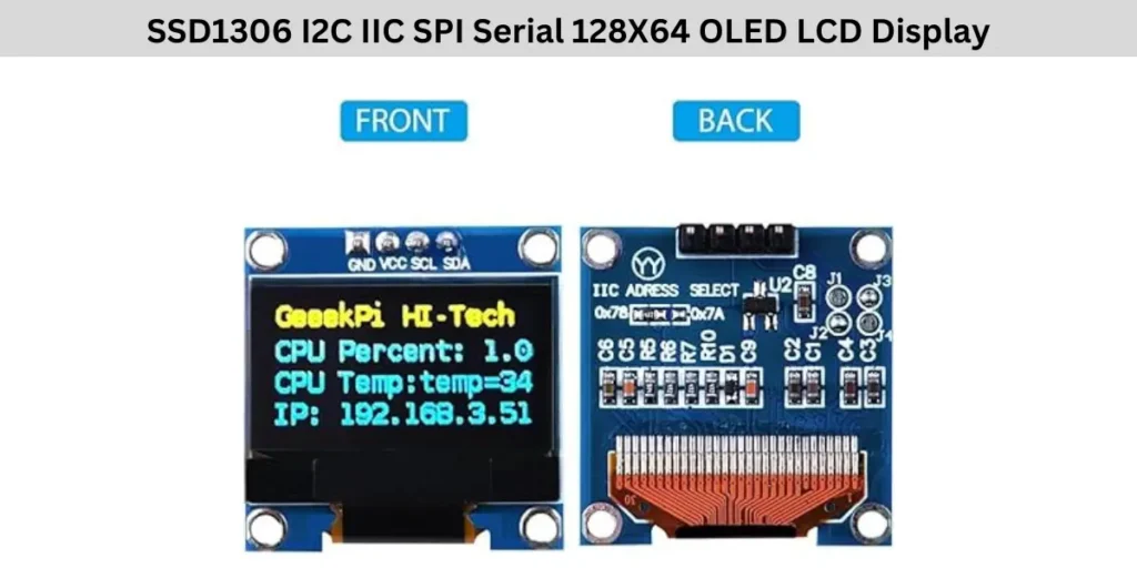
| I2C OLED LCD Display | 1 | SSD1306 |
| Current Sensor | 1 | CT sensor or Hall effect sensor for current measurement |
| Push Buttons | 3 | For user input and interaction |
| Resistor (10KΩ) | 1 | Used in voltage divider circuits |
| Resistor (47Ω) | 1 | Used for current sensor signal conditioning |
| Capacitor (0.1µF/1µF) | 1 | For signal stabilization |
| Connecting Wires | Multiple | For making electrical connections |
| 5V Power Supply | 1 | Used to power the Arduino Nano |
SSD1306 OLE Display Pinout
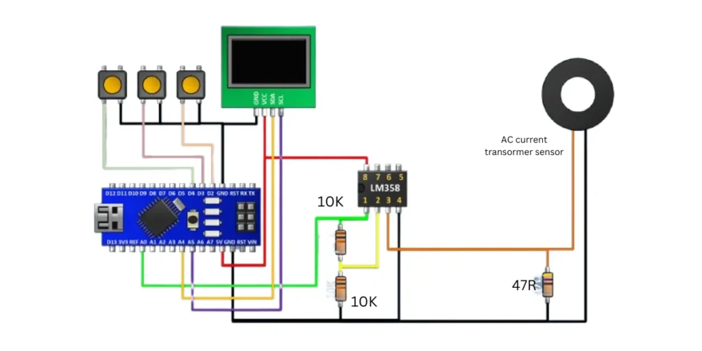
Arduino Based Clamp Meter Circuit Connection
The Arduino Based Clamp Meter Circuit consists of an Arduino Nano, LM358 operational amplifier, a I2C LCD display, Three push buttons, and a current sensor (CT sensor or Hall effect sensor).
The Arduino Nano is the main measurement section and also provides 5V DC voltage to the LCD module, LM358 IC and other components. The I2C display has four connections SDA, SCL and Positive negative supply inputs.
The LCD display is connected to the Arduino via SDA to the Arduino Pin A4 and SCL Pin to A5 Pin of Arduino for I2C communication. The 5V DC voltage is VCC and GND connected to the Arduino’s 5V and GND pins respectively.
The circuit includes three push buttons, each connected to digital pins of Arduino which are D2, D3, and D4, with common ground to GND. The LM358 op amp is powered by the Arduino’s 5V (VCC on pin 8) and GND on pin 4. The non-inverting input pin 3 of the LM358 gets the signals from the current sensor when a device is working, while the inverting input (pin 2) is connected to a voltage divider.
The amplified output (pin 1) is sent to the Arduino’s A0 analog input for processing and calculating the current usage. The current sensor detects electrical current and generates a small voltage, which the LM358 will detect and process before being read by the Arduino.
The Arduino processes this data and displays the results on the LCD display. The three push buttons will help user to interact with the circuit while checking the current. This circuit is very small and useful for real time current measurement of AC voltage.
Also Check: Digital AC Volt and Amp Meter Circuit
Arduino Nano Clamp Meter Programming Code
#include <Wire.h>
#include "Adafruit_VL53L0X.h"
#include <SPI.h>
#include <Adafruit_GFX.h>
#include <Adafruit_SSD1306.h>
#include <EEPROM.h>
Adafruit_SSD1306 display = Adafruit_SSD1306();


int b1,m,j;
float amp;
long sensorI = 0;
int8_t ic;

bool st;
void setup() {
pinMode(2,INPUT_PULLUP);
pinMode(3,INPUT_PULLUP);
pinMode(4,INPUT_PULLUP);
 // lcd.begin(16, 2);
Serial.begin(9600);
 display.begin(SSD1306_SWITCHCAPVCC, 0x3C);  // initialize with the I2C addr 0x3C (for the 128x32)
  // init done
 display.clearDisplay();


  Wire.begin();
 // lcd.print(" ampAGE: 000V ");
ic=EEPROM.read(0);
if(ic>200)ic=0;
}

void loop() {

  if(digitalRead(2)&digitalRead(3)&digitalRead(4)){
   st=0;

 if(b1>0){b1=0;
 }

  }else if(!digitalRead(2)&digitalRead(3)&digitalRead(4)&!st){
b1++;
if(b1>5){st=1;m=!m;
if(m==0)EEPROM.update(0, ic);
}
  }else if(digitalRead(2)&!digitalRead(3)&digitalRead(4)&!st){
st=1;
if(m)ic++;
if(ic>100)ic=100;
  }else if(digitalRead(2)&digitalRead(3)&!digitalRead(4)&!st){
st=1;
if(m)ic--;
if(ic<-100)ic=-100;
  }
 if(m==0){
  if(analogRead(A0)==0){
//  delay(1);
 while (analogRead(A0)<1);
 sensorI=0;
  for(int i=0;i<301;i++){
sensorI += analogRead(A0);
//if(analogRead(A1)>sensorI)sensorI = analogRead(A1);
  delay(1);
  }
  sensorI=sensorI/30;
  amp=sensorI*0.039;//0.039
amp=amp/3;

}
float amp1;
if(amp>0){
 amp1=amp+(ic*0.05);
}else amp1=0;

Serial.println(amp);

 display.setTextSize(3);
  display.setTextColor(WHITE);
 display.clearDisplay();
      display.setCursor(15,0);
display.print(amp1);
      display.print("A");
      display.display();}

else{
 float amp1=amp+(ic*0.05);
display.setTextSize(1);
  display.setTextColor(WHITE);
 display.clearDisplay();
      display.setCursor(0,0);
      display.print("Calibration");
      display.setTextSize(3);
      display.setCursor(30,10);
display.print(amp1);
      display.print("A");
      display.display();
}
}