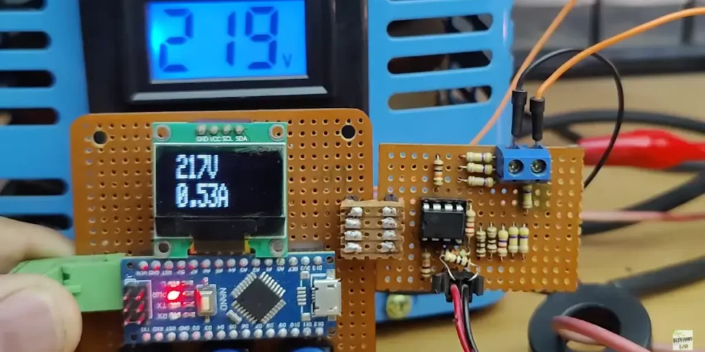
This AC voltage and amp meter helps to find the current and voltage of a device working in AC power, which is connected through this circuit. A very few numbers of electronic components are required to build this project. You need two main components which are Arduino Nano and LM358 Op-Amp. The other components are listed in the components list section.
Why is this AC Volt and Amp meter circuit used?
This circuit is designed to measure AC voltage and current from a power source and display the values on an Oled display. We can use this circuit in AC power monitoring applications, home automation, and electrical load analysis.
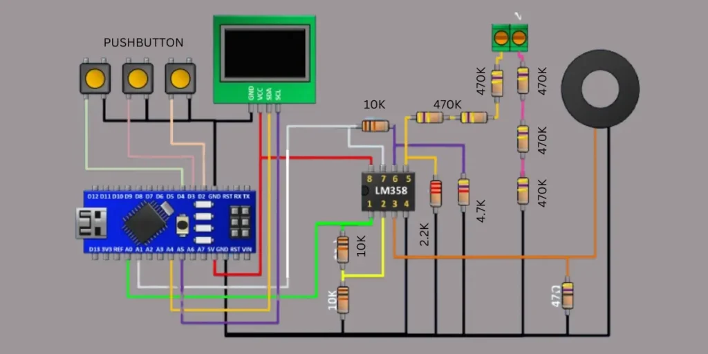
Digital AC Volt and Amp meter circuit Diagram
Components Required
| Component | Quantity | Description |
|---|---|---|
| Arduino Nano | 1 | Microcontroller for processing sensor data |
| LM358 Op-Amp | 1 | Dual operational amplifier for signal conditioning |
| Oled display | 1 | Oled display SSD1306 |
| Push Buttons | 3 | User input for calibration or mode selection |
| Current Transformer (CT) | 1 | Toroidal coil for measuring AC current |
| Resistor 470KΩ | 6 | Used in voltage divider for scaling AC voltage |
| Resistor 4.7KΩ | 1 | Part of the voltage divider circuit |
| Resistor 10KΩ | 3 | Used for signal conditioning and pull-down resistors |
| Resistor 2.2KΩ | 1 | Used for current sensor signal processing |
| Capacitor (optional) | 1-2 | For signal smoothing (if needed) |
| Terminal Block | 1 | AC input connection point |
| Wires & Connectors | Multiple | Used for making electrical connections |
AC Volt and Amp Meter Circuit Connection
The circuit was designed with an Arduino Nano, an LM358 operational amplifier, an Oled display (I2C interface function), push buttons, a current sensor (toroidal coil), and various resistors. The values of the components are given in the components list.
The Arduino Nano is the main component to performing the calculations to display how much voltage and current is used. The Arduino Nano receives the input signals from the LM358 IC. The Oled display is connected to the Arduino Nano via the I2C interface using the SDA and SCL pins. The push buttons are connected to the digital input pins of the Arduino Nano and are used for user interactions, such as calibration or switching display modes.
The voltage measurement is achieved using a resistor voltage divider network consisting of 470KΩ. This resistor connection will lower the AC voltage from high AC voltage to a safe level suitable for the Arduino’s analog input pins (A0, A1, etc.).
The current measurement is performed using a current transformer, which will detect the AC current flowing through a wire. The output signal from the CT is processed by the LM358 op-amp, which amplifies and conditions the signal before feeding it to the Arduino nano input pins. Additional resistors, including 10KΩ and 2.2KΩ resistors, help fine-tune the signal conditioning.
The power connections for the coil and LM358 are taken from the Arduino Nano 5V output pins. The ground (GND) connections are shared across all components to maintain a common ground connection. The processed voltage and current readings are then displayed on the LCD screen. The circuit is designed to provide real-time monitoring of AC voltage and current. This circuit is useful for electrical load analysis and power measurement in home applications.
AC Volt and Amp Meter Arduino Nano Programming Code
#include <Wire.h>
#include "Adafruit_VL53L0X.h"
#include <SPI.h>
#include <Adafruit_GFX.h>
#include <Adafruit_SSD1306.h>
#include <EEPROM.h>
Adafruit_SSD1306 display = Adafruit_SSD1306();


int volt,b1,m,j;

long sensorV = 0;
float amp;
long sensorI = 0;
int8_t ic, vc;

bool st;
void setup() {
pinMode(2,INPUT_PULLUP);
pinMode(3,INPUT_PULLUP);
pinMode(4,INPUT_PULLUP);
 // lcd.begin(16, 2);
Serial.begin(9600);
 display.begin(SSD1306_SWITCHCAPVCC, 0x3C);  // initialize with the I2C addr 0x3C (for the 128x32)
  // init done
 display.clearDisplay();


  Wire.begin();
 // lcd.print(" VOLTAGE: 000V ");
vc=EEPROM.read(0);
if(vc>200)vc=0;
ic=EEPROM.read(1);
if(ic>200)ic=0;
}

void loop() {

  if(digitalRead(2)&digitalRead(3)&digitalRead(4)){
   st=0;

 if(b1>0){b1=0;
 if(m==1)m=2;
 else if(m==2)m=1;
 }

  }else if(!digitalRead(2)&digitalRead(3)&digitalRead(4)&!st){
b1++;
if(b1>5){st=1;m=!m;b1=0;
if(m==0){EEPROM.update(0, vc);EEPROM.update(1, ic);}
}
  }else if(digitalRead(2)&!digitalRead(3)&digitalRead(4)&!st){
st=1;
if(m==1)vc++;
else if(m==2)ic++;
else j++;
if(j>2)j=0;
if(vc>100)vc=100;
if(ic>100)ic=100;
  }else if(digitalRead(2)&digitalRead(3)&!digitalRead(4)&!st){
st=1;
if(m==1)vc--;
else if(m==2)ic--;
else j--;
if(j<0)j=2;
if(vc<-100)vc=-100;
if(ic<-100)ic=-100;
  }
 if(m==0){
  if(analogRead(A1)==0){
//  delay(1);
 while (analogRead(A1)<1);
 sensorV=0;
  for(int i=0;i<301;i++){
sensorV += analogRead(A1);
sensorI += analogRead(A0);

  delay(1);
  }
  sensorV=sensorV/30;
  volt=sensorV*0.482;
//volt=volt/10;
  sensorI=sensorI/30;
  amp=sensorI*0.039;//0.039
amp=amp/3;
}
float amp1;
if(amp>0){
 amp1=amp+(ic*0.05);
}else amp1=0;
int volt1;
if(volt>0){
 volt1=volt+vc;
}else volt1=0;

Serial.println(volt);
if(j==0){
 display.setTextSize(2);
  display.setTextColor(WHITE);
 display.clearDisplay();
      display.setCursor(15,0);
display.print(volt1);
      display.print("V");
      display.setCursor(15,17);
display.print(amp1);
      display.print("A");}
if(j==1){
 display.setTextSize(3);
  display.setTextColor(WHITE);
 display.clearDisplay();
      display.setCursor(15,0);
display.print(volt1);
      display.print("V");
       display.setTextSize(1);
      display.setCursor(15,23);
display.print(amp1);
      display.print("A");}
if(j==2){
 display.setTextSize(3);
  display.setTextColor(WHITE);
 display.clearDisplay();
      display.setCursor(15,0);
display.print(amp1);
      display.print("A");
       display.setTextSize(1);
      display.setCursor(15,23);
display.print(volt1);
      display.print("V");}
      display.display();

      }

else if(m==1){
 int volt1=volt+vc;
display.setTextSize(1);
  display.setTextColor(WHITE);
 display.clearDisplay();
      display.setCursor(0,0);
      display.print("Calibration");
      display.setTextSize(3);
      display.setCursor(30,10);
display.print(volt1);
      display.print("V");
      display.display();
}
else if(m==2){
 float amp1=amp+(ic*0.05);
display.setTextSize(1);
  display.setTextColor(WHITE);
 display.clearDisplay();
      display.setCursor(0,0);
      display.print("Calibration");
      display.setTextSize(3);
      display.setCursor(30,10);
display.print(amp1);
      display.print("A");
      display.display();
}
}
Also Check: Arduino Clamp Meter Circuit: DIY Guide for Current Measurement