Introduction
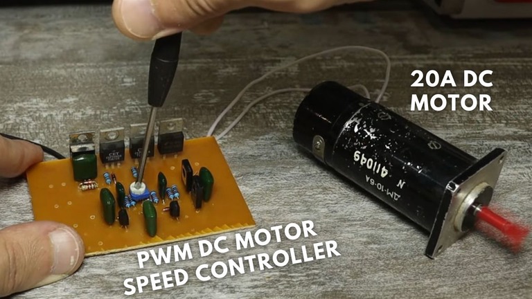
The PWM DC motor speed controller is widely used method for regulating the speed of a DC motor. This technology operates by rapidly switching the motor’s power on and off at a fixed frequency while adjusting the duration of the “on” time pulses. Today i am going to show a PWM based 20A DC motor controller circuit and its detailed here. Let’s explore the working principle of PWM DC motor speed controllers in more detail.
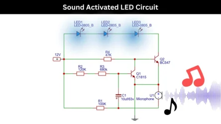
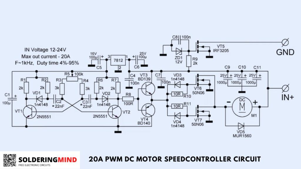
20A PWM DC motor speed controller circuit
Working principle
Generation of PWM Signal
The first step in the PWM DC motor speed control involves generating a PWM signal. This task is typically accomplished using a microcontroller or a dedicated PWM controller or transistor circuit.
The generated digital signal consists of pulses, and the duty cycle of the PWM signal represents the percentage of time the signal is “on” or high compared to the total time period of the signal.
Filtering and Amplification
Once the PWM signal is generated, it undergoes a filtering process to smoothen out any sharp edges and convert it into a continuous analog voltage signal.
This filtered signal is then amplified to a level suitable for driving the motor effectively using power Mosfets. Amplification ensures that the signal provides the necessary current and voltage levels required by the motor.
Motor Control
The amplified PWM signal is connected to the DC motor through a motor driver circuit. The motor driver circuit handles the task of providing the required current and voltage levels to operate the motor.
By adjusting the duty cycle of the PWM signal, the average voltage supplied to the motor can be regulated, allowing control over the motor’s speed.
Speed Feedback (Optional)
In more advanced setups, a speed feedback mechanism can be incorporated to measure the actual motor speed. This feedback information can come from devices such as encoders or tachometers.
By utilizing this feedback, the PWM signal can be dynamically adjusted to maintain the desired motor speed, even when the load on the motor changes. This feedback loop ensures accurate and responsive speed control.
Conclusion
These 20A PWM DC motor speed controllers offer a reliable and efficient means of controlling the speed of DC motors.
By modulating the duty cycle of the PWM signal, the average voltage supplied to the motor can be adjusted, allowing precise speed regulation.
These controllers find applications in various fields such as robotics, industrial automation, electronic vehicle speed control, and more, where accurate motor speed control is essential.