This LED Delay OFF circuit is designed in simple designing and very few number of electronic components are needed. When pressing the push button on the circuit, 12V LED turns ON and it Turns OFF after particular timing it is called LED Delay OFF Circuit.
What is LED Delay OFF Circuit
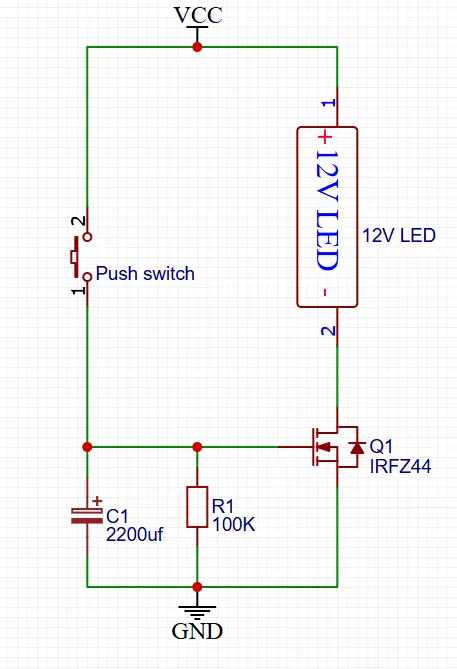
This circuit is a delay OFF LED circuit that keeps a 12V LED turned ON for a short time even after the push button is released. It uses an N-channel power MOSFET (IRFZ44) along with an RC timing network formed by a resistor and capacitor. This LED delay OFF circuits are commonly used in stairway lights, emergency lights, and power saving delay applications.
Circuit Diagram
Components Required to Build
| Component | Value / Part Number |
|---|---|
| Q1 | IRFZ44 |
| LED | 12V LED |
| R1 | 100kΩ |
| C1 | 2200µF |
| Push Switch | Momentary switch |
| Power Supply | 12V DC |
Irfz44n To-220 N-Channel 49A 55V Transistor Mosfet – Pack of 2
As an Amazon Associate, I earn from qualifying purchases.
Circuit Description
In this given circuit a 12V LED is connected to the positive supply of the connection, marked as VCC and the other end of the LED connected to the drain pin of IRFZ44 Mosfet.
The source pin of the IRFZ44 is connected to the ground supply. This MOSFET is acts like a switch in this circuit. The MOSFET gate pin is controlled by a push button and an RC network consisting of resistor R1 (100kΩ) and capacitor C1 of 2200µF.
The capacitor and resistor together determine the delay time of how long the LED stays ON after the button is released.
Working Principle
The working principle of this circuit is easy to understand. When the push button is pressed, the gate pin of the IRFZ44 MOSFET receives a positive voltage from the 12V power supply rail. At the same time the capacitor C1 gets charges quickly. This will raise the gate voltage above the MOSFET’s threshold level. This turns the MOSFET ON state and allows the current to flow through the LED. Then the LED lights up immediately.
When the push button is released, the supply is disconnected from the gate pin. But the capacitor C1 does not discharge instantly. Instead, it will slowly discharge the capacitor charge through resistor R1. As long as there is sufficient voltage at the gate, the MOSFET remains ON and the LED continues to glow.
Once the capacitor charge is falls below the MOSFET’s gate threshold voltage, the MOSFET turns OFF and cutting the current supply to the LED. The LED then turns OFF after a delay. The delay time is depends on the values of resistor R1 and capacitor C1. Increasing either value increases the OFF delay time.
Applications
- Staircase and corridor lighting.
- Delay based power control circuits.
- Emergency or backup lighting systems.
- Automotive interior lighting delay.