In this article I’m sharing the light sensor based dark detector circuit using an op- amp IC. This circuit turns ON the relay at sunset and turns off the relay at sunrise. Very simple and easy to build at home. This circuit uses basic electronics components, so you can get it from any electronics components shop easily.
LM741 op amp can easily detect the changes in ambient light and can control the external load such as a relay. This type of circuit is used in automatic street lights, security systems and light activated switches. The circuit converts light intensity variations into an electrical signal and compares it with a preset reference level of op amp.
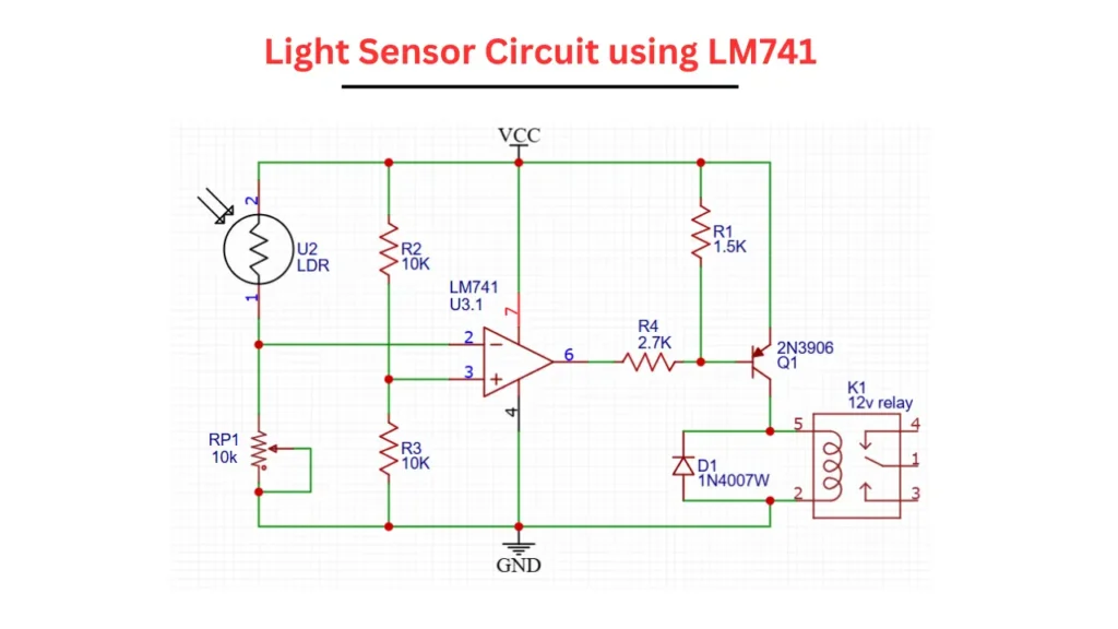
Light Sensor Circuit using LM741 Circuit Diagram
220 V Auto Day/Night on and off Photocell, LDR Sensor Switch (6 A) for Lighting
As an Amazon Associate, I earn from qualifying purchases.
Overview of LM741 OP amp
The LM741 is a popular and cheap op amp IC. It is commonly used in many analog electronic circuits. In this dark detector circuit the LM741 IC is configured as a voltage comparator.
This IC compared the voltage coming from the voltage divider, here the voltage divider is LDR and connected to a 10K potentiometer. This will be compared with the reference voltage. Based on the voltage difference in the IC will turn ON and OFF Relay in this light sensor circuit.
Components Required to Build this Circuit
| S.No | Component Name | Value / Part Number |
|---|---|---|
| 1 | Operational Amplifier | LM741 |
| 2 | Light Dependent Resistor | LDR |
| 3 | Resistor R1 | 1.5 kΩ |
| 4 | Resistor R2 | 10 kΩ |
| 5 | Resistor R3 | 10 kΩ |
| 6 | Resistor R4 | 2.7 kΩ |
| 7 | Preset Potentiometer | 10 kΩ (RP1) |
| 8 | PNP Transistor | 2N3906 |
| 9 | Diode | 1N4007 |
| 10 | Relay | 12V SPDT |
| 11 | Power Supply | 9V-12V DC |
Circuit Working Principle
When the lights falling on the LDR change its resistance value. In brighter light, the LDR resistance is low and in darkness the resistance of LDR is increased. This is the basic detection for darkness.
The LDR and 10K preset pot form a voltage divider circuit. The connection is taken from this voltage divider and it is connected to one input of the LM741 IC. The other input of the LM741 fixed reference voltage, it is set by the resistors of R2 and R3. You can manually calculated the voltage of voltage divider using free online voltage divider Vout calculator.
When the voltage from the LDR crosses the fixed reference voltage level, the LM741 IC output will change its state. This output drives the 2N3906 transistor through resistor R4 connected to the base. This will turn the relay ON or OFF depending on the light condition.
Role of 10K preset in this Circuit
The LDR connected 10K preset pot is used for fine adjustment of light sensitivity. When rotating the 10 pot, you can set the exact light level at relay On or OFF. This can gives user to get more controlling over the circuit function.
Relay Driver Stage
The relay driver stage is composed of 2N3906 PNP transistor, 12V relay and 1N4007 diode. The output IC signal has no enough current to Turn ON relay so a PNP transistor is used as a current amplifier. Protection Diode For Relay to Save Electronic Components | You Know How? The 1N4007 diode is protecting the transistor from back EMF produced by the Relay coil.
Applications
- Automatic street light control.
- Light activated alarms.
- Day/night switch circuits.
- Garden and outdoor lighting systems.
- Educational electronics projects.