

Automatic night lights are everywhere, and this type of LED lights are costly. So lets build a 1 watt LED based simple light sensor circuit using a BC547 transistor. This circuit is designed with a few electronic components and it detects the light sensitivity and automatically turns the LED light when it’s dark.
The circuit contains LDR (light dependent resistor), BC547, BC639 and 1W LED. This project is very easy to build and beginner friendly. This article shares the circuit diagram, working and components list to build this project.
What is a Light Sensor Circuit?
This light sensor circuit is designed using the LDR. It detects the light intensity and changes the LDR resistance based on the falling light intensity. The LDR shown two condition in bright light and darkness, which are
- In bright light > LDR resistance lowered
- Darkness > LDR has high resistance.
Based on the resistance, the change will turn ON and OFF the first connected BC547 NPN transistor. Which will lead to the 1 Watt LED turn ON and OFF.
Simple Light Sensor Circuit Diagram
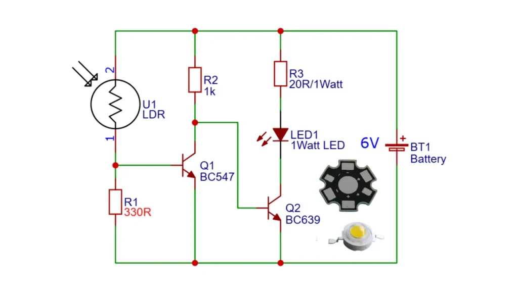
Circuit Diagram Explanation
This circuit contains very few electronic components. This works in a 6V DC power supply, You can use a battery or 6V AC to DC adapter to power the entire circuit. The main transistors include BC547 and BC639.
The BC547 is used to detect the light and signal amplification. The BC639 is used to drive the 1 watt LED light. In daylight, the LED remains OFF. When darkness is detected, the LED turns ON automatically.
Components Required
| Component | Description |
|---|---|
| Q1 | BC547 NPN Transistor |
| Q2 | BC639 NPN Power Transistor |
| LDR | Light Dependent Resistor |
| R1 | 330Ω |
| R2 | 1kΩ |
| R3 | 20Ω / 1W |
| LED | 1W High Power LED |
| Battery | 6V DC |
Working Principle
The LDR and the resistor R1 form a voltage divider. In bright light conditions, the LDR resistance is going to low and the positive voltage is passed through the LDr and turn On the BC547 transistor. When the BC547 is On means it will conducts the negative voltage and turn OFF the BC639 transistor
- Light condition the BC547 remains ON.
- Dark condition: LDR resistance increases. Base positive voltage decreases.
The resistor R3 limits the current passing through the LED and protects it from overcurrent damage.
Why BC547 and BC639 Are Used Together
- BC547 is used for low current sensing applications, so here The BC547 is the LDR light sensitivity based switching circuit.
- BC639 can able to handle the higher current required by the power LEDs.
Applications
- Automatic street light controller.
- Night lamp and emergency lighting.
- Garden and outdoor lighting systems.
- Energy saving home lighting.
- Staircase and corridor lights.