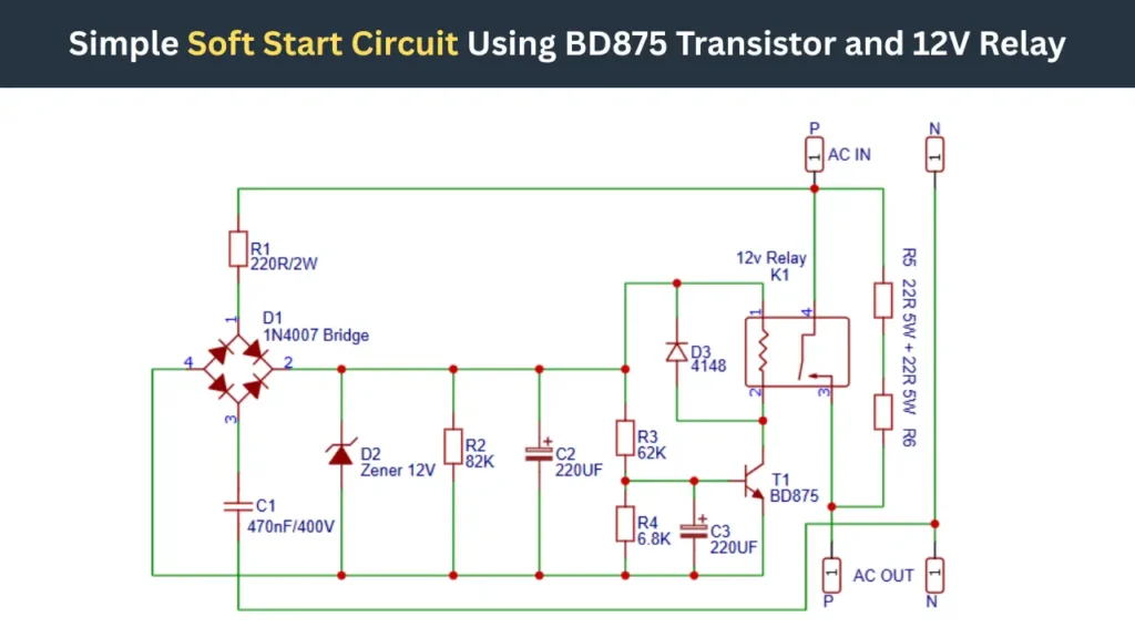
In this article, I’m sharing a simple soft start circuit for an amplifier and an incandescent lamp to limit the sudden surge of inrush current. This circuit is built with a BD875 NPN transistor, a 12V relay, and some capacitors and resistors. The project diagram, components list, and useful information’s are discussed hear.
Simple Soft Start Circuit Diagram
Components Required
| Designator | Component Name / Part Number | Description / Specifications | Quantity |
|---|---|---|---|
| R1 | Resistor | 220Ω, 2W power resistor | 1 |
| R2 | Resistor | 82KΩ, standard resistor | 1 |
| R3 | Resistor | 62KΩ, standard resistor | 1 |
| R4 | Resistor | 6.8KΩ, standard resistor | 1 |
| R5 | Power Resistor | 22Ω, 5W wirewound resistor | 1 |
| R6 | Power Resistor | 22Ω, 5W wirewound resistor | 1 |
| C1 | Capacitor | 470nF, 400V capacitor | 1 |
| C2 | Electrolytic Capacitor | 220µF, polarized capacitor | 1 |
| C3 | Electrolytic Capacitor | 220µF, polarized capacitor | 1 |
| D1 | Bridge Rectifier (1N4007 × 4) | Full-wave rectifier bridge using four 1N4007 diodes | 1 |
| D2 | Zener Diode | 12V Zener diode | 1 |
| D3 | Diode (1N4148) | Fast switching diode for relay protection/timing | 1 |
| T1 | Transistor | BD875 NPN transistor | 1 |
| K1 | Relay | 12V SPDT relay | 1 |
| AC IN | Input Terminal | AC mains input connection | 1 |
| AC OUT | Output Terminal | AC output to load | 1 |
Role of Each Component in the Circuit Design
| Component | Role in the Circuit Design | Simple Explanation |
|---|---|---|
| R1 (220R/2W) | Limits current to the rectifier section | Protects the components by reducing the excess input current, inrush current. |
| R2 (82K) | Part of timing network | Controls capacitor charging speed and startup delay. |
| R3 (62K) | Bias resistor for transistor control | Helps to trigger the BD875 transistor at the correct time. |
| R4 (6.8K) | Timing and bias resistor | Stabilizes the transistor switching behavior. |
| R5 + R6 (22R/5W) | Inrush current limiting resistors | Reduce the high startup current to protect the load. |
| C1 (470nF/400V) | Noise filtering / AC smoothing | Helps suppress the voltage spikes and interference. |
| C2 (220µF) | Timing capacitor | Creates a startup delay before relay activation. |
| C3 (220µF) | Timing and transistor stabilization | Smooths voltage and improves. |
Working Principle of the BD875 Soft Start Circuit
- When the Ac current is connected it initially passed through the 22 ohms 5Watt resistors and initial limited voltage gets to turn On the Ac device or amplifier transformer.
- The AC voltage is also passed through the 220 ohms 2 watt resistor and 470nf/400v capacitor. This transformer less power supply gives the required voltage to turn ON the relay.
- Capacitors C2 and C3 charging gradually through the connected resistors of R2, R3, and R4. Which will creating a delay period after power on.
- When the capacitors charged it releases the energy to the BD875 transistor base pin and which turns ON the Realy.
- This time the relay contact get connected with the MAIN AC line path and large current passing through the Relay contacts. Fully ac power is reaches to the device.
Why Inrush Current Protection Is Important
Inrush current is not good, which will damages the electronic components and amplifier transformer also. So limiting the initial sudden surge of current is important to increase its lifespan. So the inrush correct protection device of soft start circuit is a nice idea.
BD875 Transistor Specifications and Suitability
The BD875 is a NPN transistor comes in TO-126 packaging. This transistor can handle 45V collector-emitter voltage and maximum collector current of 1A. So it is a perfect choice for relay switching and good heat dissipation.
Function of the 12V Relay in the Soft Start Mechanism
Initially the relay is in OFF state and No current is passing through it, only the limited current is passing through the 22 ohms 5 watt resistor. which will reduce the chance of sudden inrush of current to the device. When the transistor is turn On with a delay that time relay get activated and full Ac load get connected with the device.
Advantages of Using a Soft Start Circuit
- Reduces inrush current
- Protects transformers
- Extends component lifespan
- Prevents fuse blowing
🧷Also Check – Soft Start Circuit for Amplifier Transformer Without Relay