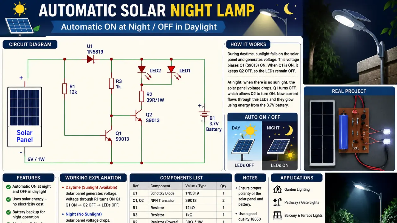
This automatic solar lamp circuit turns ON when Dark and Turns OFF at day time. This circuit also included a battery charging connection, so in day time Battery get charged and when it dark the battery charge release to the white LED lights. This circuit is very simple and easy to build at low cost.
What Is an Automatic Solar Night Lamp Circuit?
The automatic solar night lamp circuit is very simple solar operated lamp circuit. This circuit turn On the LED at night and Turn Off it and charge the lithium ion battery at Day time. The process is continuous every day.
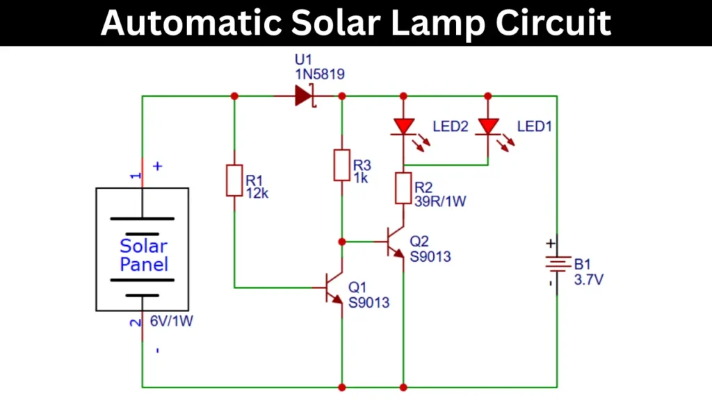
Low-Cost Automatic Solar Lamp Circuit Diagram
Components Required
| Ref. No. | Component | Value / Specification | Quantity |
|---|---|---|---|
| U1 | Schottky Diode | 1N5819 | 1 |
| Q1 | NPN Transistor | S9013 | 1 |
| Q2 | NPN Transistor | S9013 | 1 |
| R1 | Resistor | 12k, 1/4W | 1 |
| R2 | Power Resistor | 39R, 1W | 1 |
| R3 | Resistor | 1k, 1/4W | 1 |
| LED1 | LED | White LED (3mm/5mm) | 1 |
| LED2 | LED | White LED (3mm/5mm) | 1 |
| B1 | Rechargeable Battery | 3.7V Li-ion (18650) | 1 |
| Solar Panel | Photovoltaic Panel | 6V, 1W | 1 |
Role of Each Component in the Circuit Design
| Component | Value | Role in the Circuit |
|---|---|---|
| Solar Panel | 6V / 1W | Converts the sunlight into electrical energy and powers the circuit during daytime, also charging battery. It also acts as a light sensor to detect day and night conditions. |
| U1 (Schottky Diode) | 1N5819 | this diode will prevents the reverse current flow from the battery back into the solar panel at night, and which will reducing the power loss and protecting the battery. |
| Q1 (NPN Transistor) | S9013 | Works as a daylight detector. When sunlight is available, Q1 turns ON and controls the switching behavior of transistor Q2. |
| Q2 (NPN Transistor) | S9013 | Functions as the main switching transistor, turning the LEDs ON or OFF depending on the signal from Q1. |
| R1 (Resistor) | 12kΩ | Provides bias current to Q1 and helps determine the sensitivity of day/night detection. |
| R2 (Power Resistor) | 39Ω / 1W | Limits current flowing through the LEDs, protecting them from excessive current and extending lifespan. |
| R3 (Resistor) | 1kΩ | Controls base current to Q2, ensuring stable transistor operation and switching. |
| LED1 & LED2 | White LEDs | Produce light during nighttime when the circuit detects low or no solar panel voltage. |
| B1 (Battery) | 3.7V Li-ion Battery | Stores energy generated by the solar panel during the day and powers the LEDs at night. |
How Does the Automatic Solar Light Circuit Work?
The solar connected with the circuit gives 6V at day time and the transistor Q1 get activated and turn OFF the Q2 transistor. so their is no current passing through the Q2 transistor then the LED remain OFF.
In night time, the voltage supply is stopped from the solar panel and the Q2 transistor get activated by getting base voltage from 3.7V battery through the 1K resistor. Then the result the current passing through the LED and lamp lights.
🧷 Also Check – Other Solar panel project