

Building Radio circuit is interesting and rewarding process, So I decided to give a simple transistor radio circuit using two transistors. The circuit works on 3V DC battery and you need few number of electronic components to build this. In this article I am sharing the circuit diagram and components details.
Does This Simple Transistor FM Radio Actually Works?
Yes this FM radio circuit produce some FM reception and work well as a practical FM radio. The topology is given as Antenna > LC tuning > Regenerative detection > RF amplification > Audio extraction > Headphones
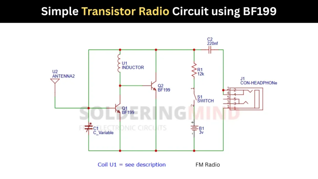
Simple Transistor Radio Circuit Diagram
Components Required for the BF199 Radio Circuit
| Component | Value / Type | Quantity | Function |
|---|---|---|---|
| Q1 | BF199 NPN RF Transistor | 1 | RF amplification / detection |
| Q2 | BF199 NPN RF Transistor | 1 | Regenerative amplification / RF stage |
| R1 | 12 k Resistor | 1 | Biasing transistor circuit |
| C1 | Variable Capacitor (5 to 30 pF typical) | 1 | Tunes FM frequency |
| C2 | 220 nF Capacitor | 1 | Audio coupling to headphone |
| U1 | Air-core Coil (4 turns CuL wire, 4 mm inner diameter) | 1 | Forms LC tuning circuit |
| U2 | Antenna (30 to 100 cm wire) | 1 | Receives FM signals |
| J1 | High impedance Earphone / Headphone Jack | 1 | Audio output |
| B1 | 3V Battery (2×AA or coin cells) | 1 | Power supply |
| S1 | SPST Switch | 1 | ON/OFF control |
| PCB / Breadboard | Optional | 1 | Circuit assembly |
Inductor Coil Specifications
| Parameter | Specification |
|---|---|
| Wire type | Lacquer-insulated copper wire (CuL) |
| Turns | 4 turns |
| Internal diameter | 4 mm |
| Core | Air core (no ferrite) |
| Wire thickness | ~0.5–0.8 mm recommended |
| Spacing | Slight spacing between turns |
How the Simple Transistor Radio Circuit Works
The FM radio signals (RF) receives through the connected antenna and selecting the frequency of FM using the LC circuit. The inductor is 4 turns air core coil you can adjust the variable capacitor will changes the LC value. The varied signal feed into the BF199 transistor base pin.
The BF199 is RF transistor and which amplifies the low FM signals to high. The second BF199 transistor is using as an additional amplification of the signal. One the FM signal extracted it converted to audio signal and passing though the 220nF coupling capacitor and reach sound in headphone.
FM radio is act like the receiver and FM transmitter which act like the signal transmitting device. Both are different. The FM station has the transmitter device through the device the FM frequency signal is broadcasting.
Antenna Selection for Better FM Signal Reception
The FM Radio antenna has crucial role in this circuit, so the selection of antenna and its length is very important. The FM radio frequency range is from 88 to 108mHz. in testing connect a 30 to 100 cm insulated copper wire to receive FM signals. Excessive long wire could attract more noise to this circuit.
Why the Circuit May Fail to Receive FM Signals
- FM circuits operate at very high frequencies, even is a small wiring mistakes or incorrect coil dimensions will prevent it from proper operation.
- incorrectly wound coil (U1)
- Weak antennas, low battery voltage, incorrect transistor orientation or poor solder joints can cause it to fail the circuit.