Weak FM radio signals can cause poor audio quality, unwanted noise and unstable reception. An FM Antenna Booster circuit helps to increase the received signal strength before sending it to the FM radio tuner. This article explains an easy and effective FM Radio Signal Booster circuit using a JFET transistor (MPF102 or NTE451).
How an FM Antenna Booster Works
FM radio signals are often weak due to,
- Long distance from the radio station
- Obstructions like buildings, hills, metal structures
- Indoor radio placement
- Short or inefficient antenna
This FM booster circuit uses a JFET RF amplifier to increase the antenna’s sensitivity and improve reception. It amplifies very low RF signals with minimal noise. You can connect this circuit to the simple transistor radio circuit to boost its signal receiving capacity.
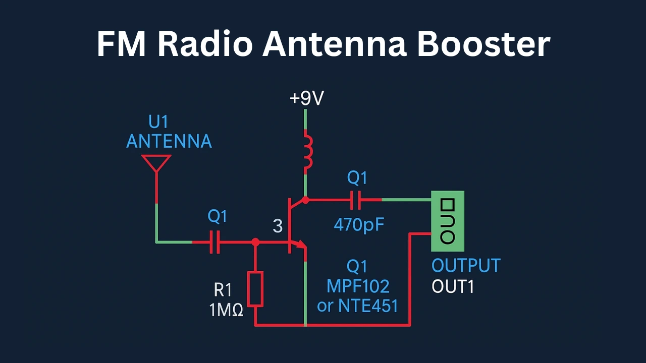
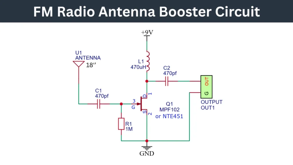
FM Radio Antenna Booster Circuit Diagram
Components Required
| Part | Value / Type | Description |
|---|---|---|
| U1 | 18 inch Antenna | FM receiving antenna |
| Q1 | MPF102 / NTE451 | JFET RF Amplifier transistor |
| L1 | 470 µH Inductor | RF choke supplying DC to the amplifier |
| C1, C2 | 470 pF Capacitors | RF coupling capacitors |
| R1 | 1 MΩ Resistor | Biasing for JFET gate |
| Supply | +9V Battery/Adapter | Power source |
| Output | OUT1 | Connects to FM radio antenna input |
Working Principle of the Circuit
The 18 inch antenna is receives the weak FM signals. The received signal is then passes through the capacitor C1 of 470 pF into the Gate pin of the JFET transistor. The resistor R1 (1MΩ) is keeps the gate at proper bias level.
The amplified RF signal from the Drain (D) is passes through the capacitor C2 of 470 pF to the output. The inductor L1 (470µH) is acts as an RF choke, this allowing the DC but blocking RF from the power supply. The amplified signal is then fed into the FM radio input.
Advantages of This FM Booster
- ✔ Improves weak FM radio signals.
- ✔ Low noise amplification due to JFET transistor is used.
- ✔ Works with home, car, or portable FM radios.
- ✔ Runs on a simple 9V battery.
- ✔ Easy to build, beginner-friendly.
How o Test this Booster Circuit
Connect the OUT1 output to your radio’s antenna input and ground to the radio ground connection. Tune your FM radio to a weak station. Next you need to Power ON the booster circuit.
Notice the better audio clarity and stronger reception. If signals over amplify or distort, reduce antenna length or increase the spacing from radio. In this way you can identify the change and test the circuit.