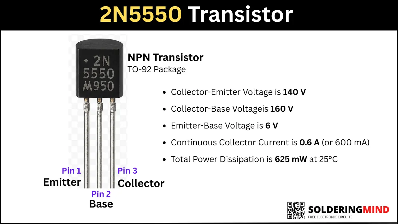
The 2N5550 is an NPN transistor that comes in TO-92 packaging. In this article, I’m sharing useful information regarding the 2N5550 pinout, equivalent transistors for replacement and its specifications.
What is the 2N5550 Transistor?
2n5550 is an epitaxial NPN transistor, which is available in a through-hole type as TO-92 plastic packaging. It has the collector to emitter voltage of 140V and 600mA collector current. Currently, the “onsemi” company has stopped manufacturing this, and you can find a similar component as the ZTX455 transistor.
2N5550 Transistor Pinout Diagram
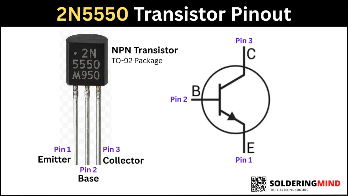
2N5550 Pin Configuration
To check the pinout and pinout configuration of this transistor, you need to hold the transistor numbering or flat side facing you, and the three pins are pointing downward. Then count the transistor’s pins from left to right as Emitter, base, and Collector. The detailed pin configuration is given in the table below,
| Pin Number | Pin Name |
|---|---|
| 1 | Emitter (E) |
| 2 | Base (B) |
| 3 | Collector (C) |
Specifications
- Collector-Emitter Voltage is 140 V
- Collector-Base Voltageis 160 V
- Emitter-Base Voltage is 6 V
- Continuous Collector Current is 0.6 A (or 600 mA)
- Total Power Dissipation is 625 mW at 25°C
2N5550 Equivalent Transistors and Replacement Options
Very closest and best replacement option is 2N5551 or BC487 transistors. and other transistors are BC639, BC637, MPSA42, 2N5833, KSP5551, BF422 used as equivalent. Always check the pinout and specifications before replacing.
How to Identify a Faulty 2N5550 Transistor
A faulty transistor is causing issues in the circuit, which shows improper switching and a weak signal in amplification. The damages part is produce more heat, and it will also damages the nearest components.
The defective transistor can be identified using a multimeter. Turn the multimeter knobs to diode mode and place the Red probe in the base pin and the black probe in the emitter or collector. The good transistor will show a value between 0.55 V and 0.75 V. If the multimeter shows the value of 0V or a very low resistance between any two pins in both directions, the transistor is likely short circuited.
Common Applications
- Used in amplifier driver stage to process the input audio signals.
- It has 600mA collector current so, it also used in LED circuits and relay driver circuits.