The LM567 is a popular Tone decoder IC and it has a stable phase locked loop to detecting the specific input frequency. for more clarity the LM567 tone decoder chip produces a simple ON or OFF signal at the output. when a specific set frequency is detected in the input pin of the IC. So in this article sharing Datasheet, Pinout and Equivalent IC information’s.
Features of LM567 Tone Decoder IC
- You can control how sensitive it is to different signal speeds.
- It ignores the input signals that are too fast or too slow.
- It doesn’t react to random or incorrect input signals.
- It keeps working at the same signal speed without drifting.
- You can set it to work with signals from very slow to very fast.
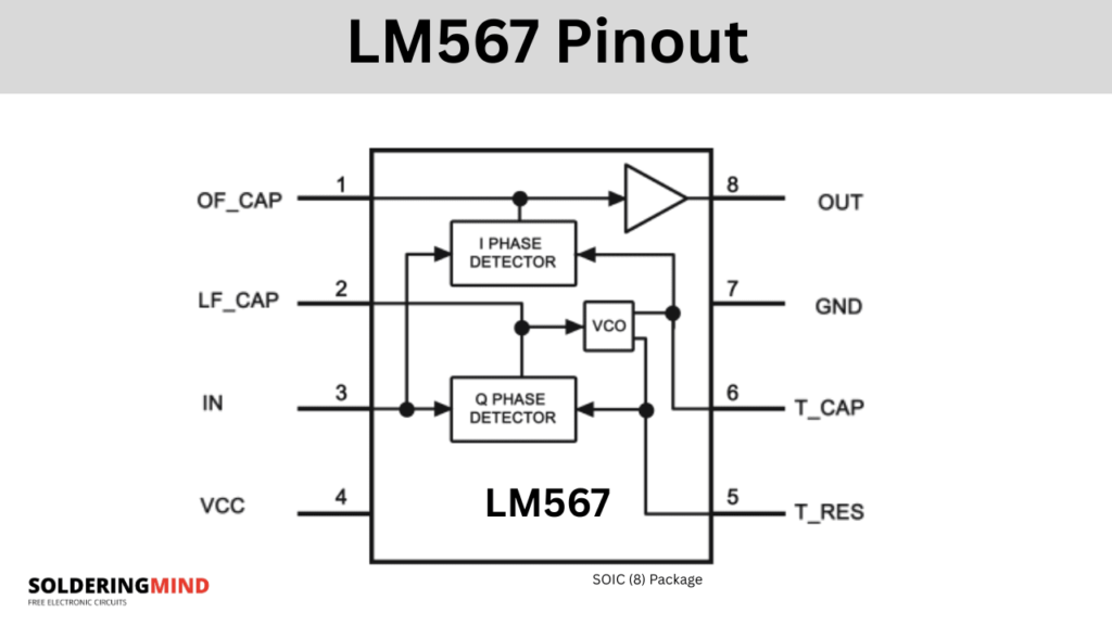
LM567 Pinout and Pin Configuration
| Pin No. | Name | Pin Description |
|---|---|---|
| 1 | OF_CAP | Output filter capacitor pin |
| 2 | LF_CAP | Loop filter capacitor pin (PLL low-pass filter) |
| 3 | IN | Signal input |
| 4 | VCC | Positive supply voltage |
| 5 | T_RES | Timing resistor connection |
| 6 | T_CAP | Timing capacitor connection |
| 7 | GND | Circuit ground |
| 8 | OUT | Logic output (open collector transistor to ground) |
Working Explained using Block Diagram

The LM567 tone decoder works on the principle of a phase locked loop (PLL). The input signal enters through the input pin and is compared with the frequency generated by an internal voltage controlled oscillator (VCO). The frequency of this VCO is set by external timing components such as a resistor and capacitor.
If the input signal frequency is close enough to the VCO frequency, the phase detector inside the IC produces a control signal that keeps the VCO locked to the input frequency. A loop filter smooths this control signal and helps determine the bandwidth of detection.
When the input signal is matches the tuned frequency range, the LM567 output changes its state. Internally, the output is an open collector transistor, which pulls the output pin low when the frequency is detected. This makes the LM567 useful for tone detection, frequency monitoring and control applications. In simple terms, it listens for a specific tone or frequency and then activates its output whenever that tone is present.
What is Phase Locked Loop (PLL) Used in LM567
A Phase Locked Loop (PLL) is an electronic control system that locks the output frequency of a voltage-controlled oscillator (VCO) to the frequency of an input signal by continuously comparing their phases. If there’s a difference, the PLL adjusts the VCO until both frequencies match and their phase difference is minimized. This makes PLLs very useful for frequency synthesis, signal demodulation, tone decoding, and keeping systems synchronized.
Center Frequency of LM357
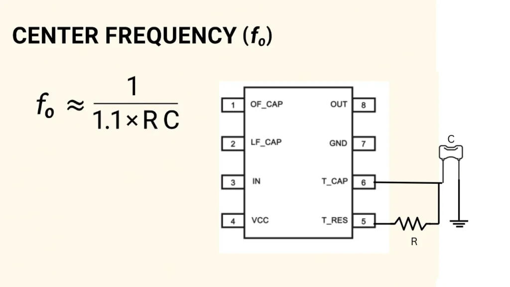
In the LM567 tone decoder IC, the “center frequency” term is using for explaining its working. The center frequency is the main frequency around which the IC is tuned to detect signals. This frequency is set by the external timing resistor and capacitor connected to the LM567 IC pins of 5 and 6.
The internal voltage controlled oscillator called as VCO is operating at this frequency. The circuit compares the input signal with fixed VCO inside of the IC. If the input is matches or is close to this center frequency, the LM567 output goes low, indicating detection.
Equivalent IC for Replacement
- NE567 – Functionally the same as LM567, often interchangeable.
- LM567CN – DIP package version of the same IC.
- LM567CM – SOIC package version.
- LMC567 – CMOS version with lower power consumption and higher oscillator frequency range.