MPF102 is a popular N channel JFET transistor used in may RF signal amplification circuits. we already shared FM radio antenna booster circuit with you, that circuit is working based on this JFET transistor as the main part of the circuit. In this article, sharing the Pinout, Equivalent and complete information’s regarding the MPF102 transistor.
What are JFETs and Why it’s used?
✅ A JFET are known as Junction Field Effect Transistor, which is a type of transistor that controls the current flow using an electric field applied to its gate terminal.
✅ Unlike bipolar junction transistors which are current controlled devices, a JFET transistor is a voltage controlled components and it offers very high input impedance, so this making it an ideal for handling delicate or weak signals without loading the source.
✅ JFETs are widely used in RF amplifiers, audio preamps, filters, oscillators and impedance buffer stages because they generate less noise and provide better signal sensitivity.
✅ It operates efficiently even at low voltages also. Their stable performance, low distortion, and simplicity of use make them a preferred choice in many analogue and communication circuits.
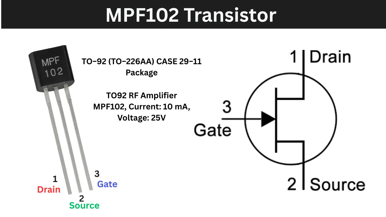
MPF102 Transistor Pinout
To correctly identify the MPF102 transistor pins, you just hold the transistor with the flat side facing you and the leads pointing downward. When you can see the writing on the flat face such as “MPF102”, this orientation ensures consistent pin identification.
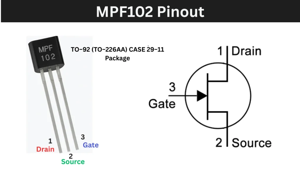
In this position, the three pins are arranged from left to right as Drain, Source and Gate. This applies to the common TO-92 package used for the MPF102 and helps avoid wiring mistakes in RF, audio or amplifier circuits.
If the transistor is rotated or held with the curved side facing you, the pin order will not be the same, so always confirm orientation using the flat face as the reference.
When working in a circuit, it’s a good practice to verify pin functions using a multi meter in diode or continuity mode, especially if the leads are trimmed short or the marking is faded.
Pinout Configuration
| Pin Position | Pin Name |
|---|---|
| Left lead | Drain |
| Center lead | Source |
| Right lead | Gate |
Proper handling prevents damage to the device and ensures correct operation in your electronic projects.
MPF102 Transistor and Maximum Rating
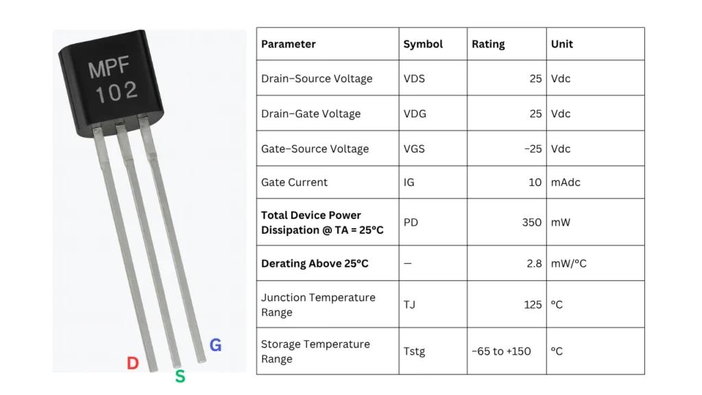
MPF102 Transistor Maximum Ratings
| Parameter | Symbol | Rating | Unit |
|---|---|---|---|
| Drain – Source Voltage | VDS | 25 | Vdc |
| Drain – Gate Voltage | VDG | 25 | Vdc |
| Gate – Source Voltage | VGS | -25 | Vdc |
| Gate Current | IG | 10 | mAdc |
| Total Device Power Dissipation @ TA = 25°C | PD | 350 | mW |
| Derating Above 25°C | – | 2.8 | mW/°C |
| Junction Temperature Range | TJ | 125 | °C |
| Storage Temperature Range | Tstg | −65 to +150 | °C |
Features of MPF102 Transistor
- N Channel JFET designed for RF and VHF amplifier applications
- Low Cut off Voltage for excellent sensitivity in weak signal reception
- High Gate Input Impedance suitable for impedance sensitive preamplifiers
- Low Noise Figure, ideal for audio and RF front end circuits
- High Gain Capability improves overall signal amplification performance
- Low Leakage Current ensuring stable operation in low-level signal stages
- Wide Operating Temperature Range: -65°C to +150°C Storage
- Low Power Dissipation makes it suitable for battery powered equipment
Equivalent of MPF102 Transistor
Several transistors can be used as equivalents or replacements for the MPF102 N Channel JFET, depending on the application. One of the closest and most commonly suggested substitutes is the 2N3819, which offers similar characteristics and is widely used in RF and VHF amplifier stages.
Other replacements include the 2N5457, 2N5458, and 2N5459, which belong to the same JFET family and can perform well in audio preamplifiers, buffer stages, and weak signal detector circuits.
The BF245A/B/C series is also a good alternative, though each variation has a slightly different current range, and may require small bias adjustments for optimal performance.
For higher frequency projects or stronger signal amplification, options like the J310 or 3N211 may provide improved gain characteristics, making them suitable for RF preamps or receiver front ends.
Commercial replacement part codes such as NTE312 or ECG312 are also available for general purpose servicing. However, it is important to note that not all replacements share the same pin configuration,
for example, devices like the J201, although useful in audio circuits, often have a different pinout, so verifying lead orientation before use is essential to avoid wiring errors.
Applications
- RF and VHF/UHF amplifier stages.
- FM radio and communication receiver front ends.
- High impedance buffer and impedance matching circuits.
- Low noise audio preamplifiers and guitar effects pedals.
- Oscillator and mixer circuits in RF designs.
- Electronic switching and analogue control circuits.
- Select 52 more words to run Humanizer.