The automatic night light circuit is a simple and very useful electronic project that turns on a light automatically when it gets dark and switches it off when it becomes bright again. This circuit is widely used in homes, garden and street lighting systems to save power energy and provide convenience of switchless manual operations.
Automatic Night Light Circuit Overview
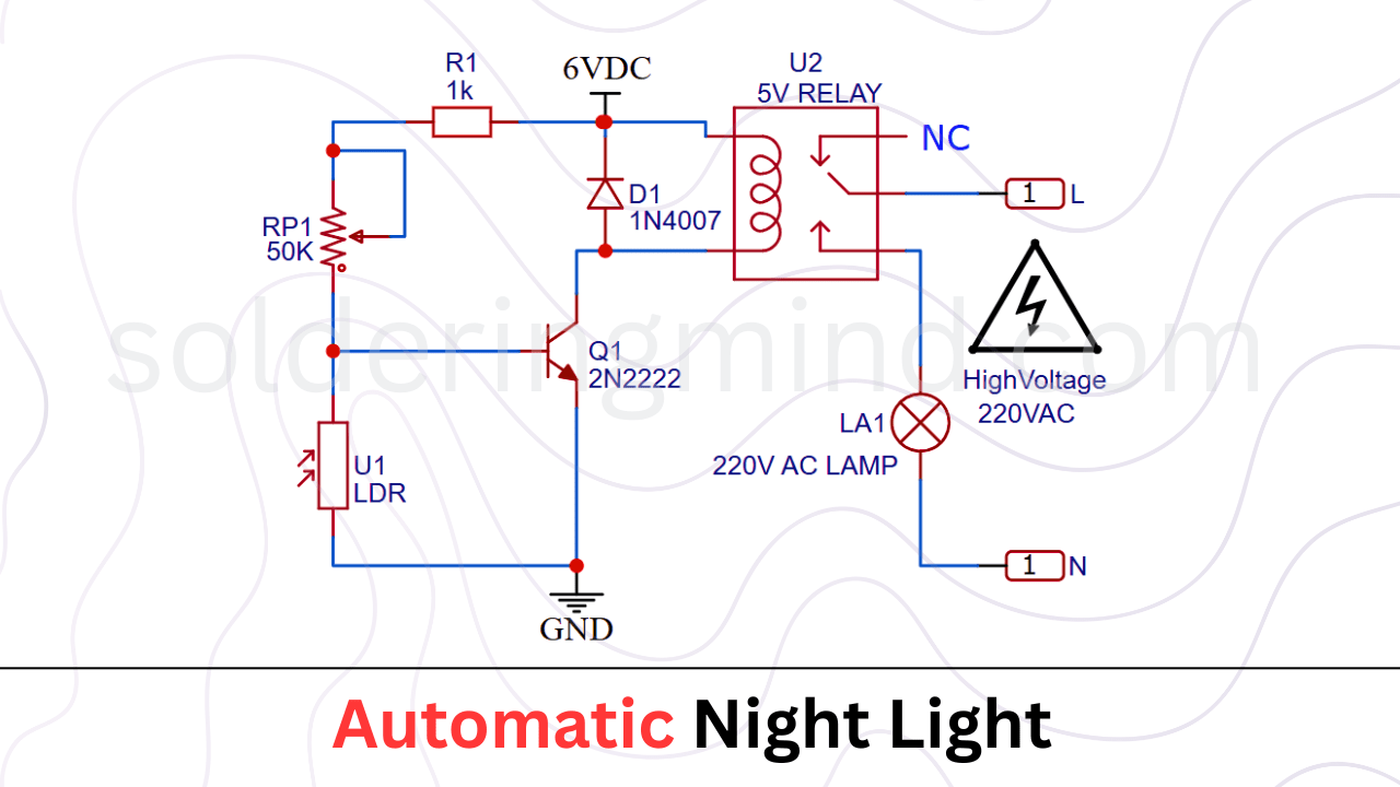
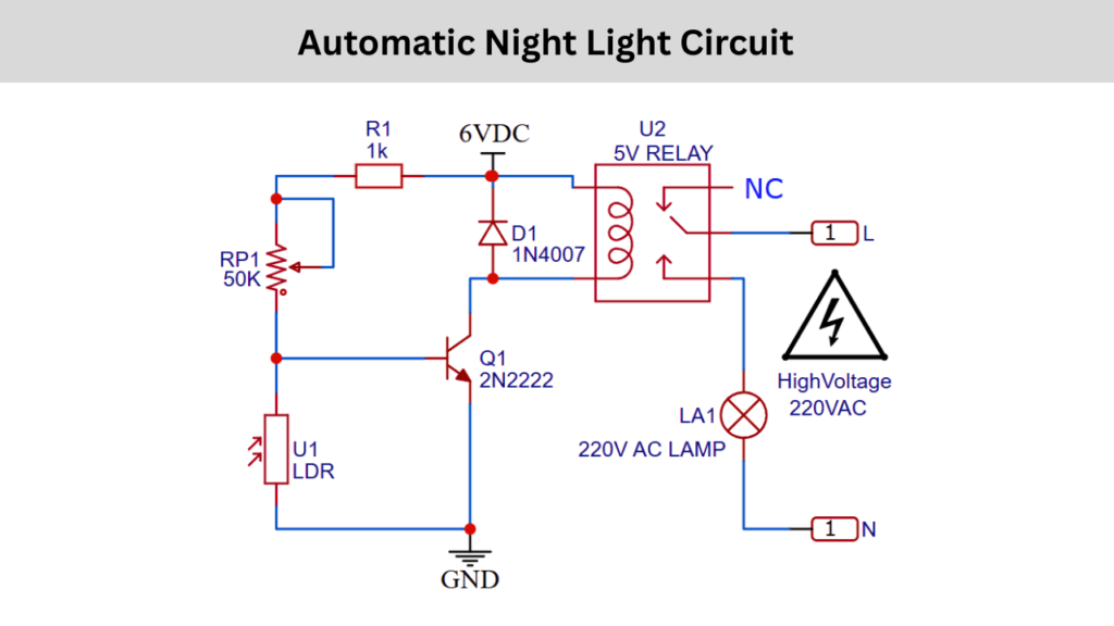
The Automatic Night Light Circuit is designed to switch a 220v AC lamp ON automatically when the surroundings area of the sensor become dark and switch it OFF when there is sufficient light falls on the LDR. The circuit mainly depends on the Light Dependent Resistor (LDR) to sense the intensity of ambient light and a transistor of 2N222 is act as an electronic switch to control the 5V relay.
A 50k variable resistor is used to adjust the sensitivity of the circuit and it allowing users to set the light level at which the lamp should turn ON or OFF. The transistor drives a 5V relay which will controls the 220V AC lamp (LA1) safely without directly exposing the low voltage control circuit to high voltage.
When it is bright, the LDR’s resistance decreases and current flowing through the LDR and more negative voltage in the transistor base pin which causing the transistor to remain OFF and the relay also in OFF state and keeping the lamp OFF. When darkness falls, the LDR’s resistance increases, allowing the transistor to turn ON and it will powering the relay and switching the lamp ON automatically.
A protection diode (D1) of 1N4007 is connected across the relay coil to prevent voltage spikes caused by the relay’s magnetic field when it switches OFF, it will protecting the transistor from potential damage.
Components Required
| Component | Quantity |
|---|---|
| U1 – LDR | 1 |
| RP1 – 50K Potentiometer | 1 |
| R1 – 1KΩ Resistor | 1 |
| Q1 – 2N2222 Transistor | 1 |
| D1 – 1N4007 Diode | 1 |
| U2 – 5V Relay | 1 |
| LA1 – 220V AC Lamp | – |
| 6V DC Supply | – |
Working Principle
The automatic night light circuit is working based on the principle of light dependent resistance (LDR) and its resistance changing based on the light falling on this component.. An LDR’s resistance decreases when the intensity of light falling on it is increases, and vice versa. This change in resistance is used to trigger the transistor to switch ON and OFF. This will makes the relay that switches the lamp ON or OFF.
Applications
- Street lights and garden lights.
- Automatic room night lamps.
- Outdoor security lighting systems.
- Industrial automation systems requiring light based control.