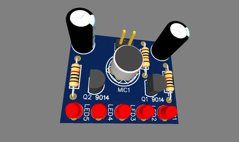
This is a voice activated LED circuit used in many DJ parties or in home audio systems. This circuit give a perfect visual appearance when you play a music and the LED will shows the rhythm in the form of light. So in this article I’m sharing the simple circuit built with two transistors and a condenser MIC, Circuit diagram and PCB Layout is shared withy you.
Voice Activated LED Circuit Diagram
Construction and Working of Circuit
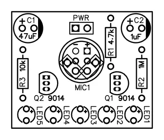
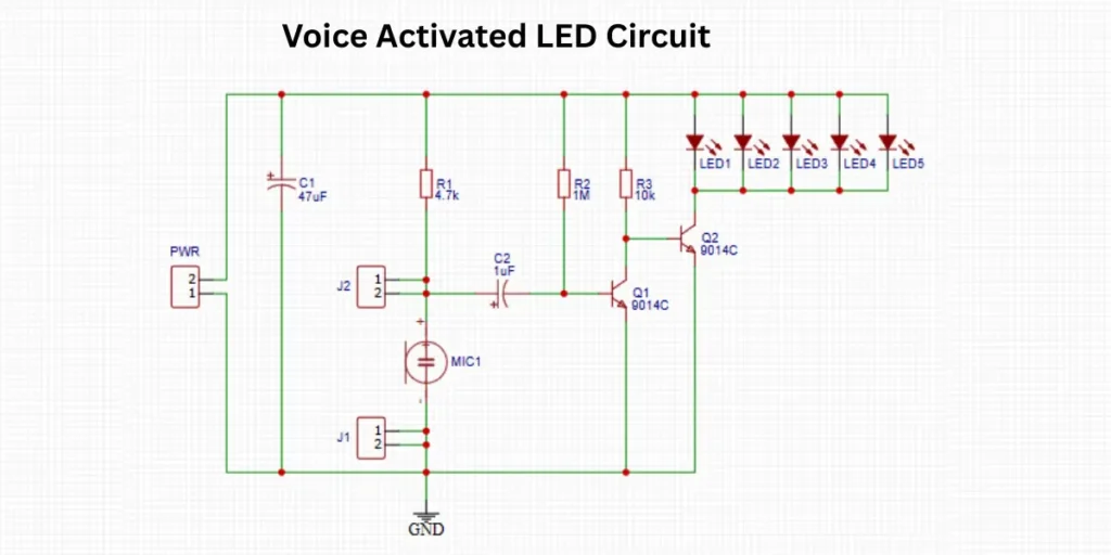
The Voice Activated LED Circuit works using a condenser microphone and a two stage transistor amplifier. The circuit is powered through the connector labeled PWR, which provides 5 volt to the circuit. The microphone (MIC1) captures the sound vibrations from the environment. Negative terminal of the microphone is connected to ground and the other is connected to the positive supply through a 4.7kΩ resistor and it also coupled to a 1µF capacitor. This capacitor sends the AC signal (voice signal) from the microphone to the base of the first transistor Q1 (9014C), which amplifies it.
A 1MΩ resistor is used from the supply line to its base. A 10kΩ resistor (R3) is placed between the collector of Q1 and the base of the second transistor Q2 (9014C). Q2 acts as a switch and drives the output load. When Q2 is activated, current flows through the five LEDs (LED1 to LED5) connected in parallel. Then the connected light turn on. The LEDs share a common line connected to the collector of Q2 and are all connected to the positive supply line.
This circuit responds to sound levels (such as a clap or voice), where the microphone’s signal is amplified and used to switch the LEDs on based on response to the detected audio input.
PCB Layout of Voice Activated LED