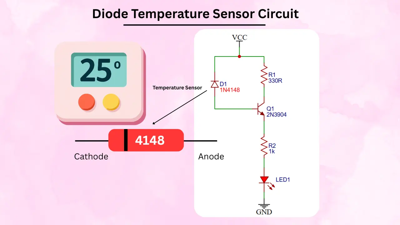
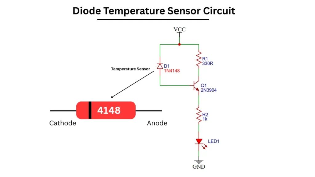
The 1N4148 diode is using as a temperature sensor in this Diode temperature sensor circuit. Connect a single transistor and LED for indication of temperature changes. This circuit consist of few number of electronic components and low cost project for hobbyist.
Diode Temperature Sensor Circuit Diagram
Components Required
| Sl. No. | Component Name | Value / Part Number | Quantity |
|---|---|---|---|
| 1 | Diode | 1N4148 diode | 1 |
| 2 | Transistor | 2N3904 | 1 |
| 3 | Resistor (R1) | 330Ω | 1 |
| 4 | Resistor (R2) | 1kΩ | 1 |
| 5 | LED | Any color | 1 |
| 6 | Power Supply | 5V / 9V DC | 1 |
Working Principle
The 1N4148 diode in this circuit is acts as a temperature sensor. This diode has its forward voltage changes with temperature increases. When the diode is forward biased it typically has a voltage drop of about 0.7 V at room temperature.
As the temperature is increases this voltage decreases at a rate of approximately -2 mV. This means the diode produces a small and predictable voltage variation depending on the surrounding temperature. So this is useful for temperature sensing applications.
This small voltage change is applied to the base of the 2N3904 NPN transistor. The transistor will amplify the input voltage. At lower temperatures, the higher diode voltage and it allows the transistor to conduct more and the same time turning the LED ON.
As temperature rises and the diode voltage drops, this will conducts less and reducing the current flow and the LED to dim or turn OFF. The resistors in the circuit help to control the current and stabilize operation.
Applications
- Used for simple visual indication (LED ON/OFF) when temperature changes.
- Can be used in power supplies, chargers, and small electronic devices to detect overheating and trigger warnings.
- Acts as a simple heat detector in low-cost alarm systems.