This low battery indicator circuit will works by glow the RED LED when the 12V battery voltage is falls down below 9.6V. This 12V low battery indicator circuit is a simple circuit working with two transistors and a Zener diode. The circuit will alert you when a 12V battery voltage is drops below a specific voltage threshold.
Components Required
| Component | Value/Part Number |
|---|---|
| Resistor (R1) | 1kΩ |
| Resistor (R2) | 1kΩ |
| Resistor (R3) | 10kΩ |
| Transistor (Q1) | BC547 |
| Transistor (Q2) | BC558 |
| Zener Diode (U1) | 9.6V |
| LED (LED1) | Red |
| Power Supply (B1) | 12V DC |
12v Low Battery Indicator Circuit
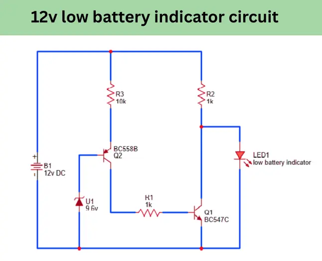
This circuit uses basic components to monitor the battery levels and activate an LED when the voltage falls too low. This simple electronic project is Ideal for DIY electronics enthusiasts, automotive battery monitoring and backup power systems. this low battery indicator helps to prevent any unexpected power failures and protects your devices from under voltage damage also by notifying you.
Construction Explanation
In this circuit a 9.6V zener diode is connected to the BC558 PNP transistor base connection in reverse bias mode. The zener diode conduct the negative voltage when the input voltage is above 9.6V. Here the zener diode is acting as a reference voltage detector for low voltage detector circuit.
The emitter pin of BC558 is connected to positive voltage using a 10K resistor. The collector pin is connected with base pin of BC547 using a 1K resistor. BC547 transistors connector is connected with Low voltage indicator LED positive side and a 1K resistor. The emitter pin goes to the ground connection.
The LED pins, cathode is connected with the negative supply of 12V DC input. The positive side to the 1K resistor and transistor connector pin.
Working Principle
The basic working principle of this circuit is turn on the Connected red LED when the input DC voltage is falls down below 9.6v. This low voltage is set by the connected 9.6V zener diode. if you want to increase the low voltage indication to 11v use a 11.2V zener diode instead of 9.6v. The working principle is explaining in two conditions which are,
- Battery voltage above 9.6V
- Battery voltage below 9.6V
Battery Voltage is Above 9.6V
When the input battery voltage is above 9.6v, in this condition the reverse bias connected zener diode start to conduct the negative voltage. The negative voltage is reaches to the base pin of BC558 PNP transistor and it starts to conduct, the current is passing from emitter to collector. The current is reaches to the next BC547 NPN transistor base pin.
The 1K resistor is limiting the current flow to the base pin. When the voltage is detected in base of BC547 it starts to conduct the negative voltage to the LED positive connection pin. In this situation the anode and cathode pin has no potential differences, so the LED remains OFF. This indicating the DC voltage is above 10V.
Battery voltage Below 9.6V
The reverse situation will happened here. When the DC input voltage is below 9.6V, the zener diode will not conduct the negative voltage to the base pin of BC558 transistor. So their is no current flow to the base pin the transistor will not turn ON. so the current flow to the BC547 is not possible. This time the LED anode connection getting positive voltage from the 1K resistor and negative from the ground connection. This time the RED LED turns On and it indicating the 12v batter voltage is below 10V.
Applications
- Automotive Battery Monitoring to inform vehicle owner about the battery voltage is low.
- In Solar Power Systems the sunlight is goes and voltage below 10v this circuit will alert.
- Inverter and UPS system for low battery indication.
- 12V lead acid battery system to inform the owner to not over discharge the battery and prevent battery damage.
FAQ
it is a indicator circuit or alert circuit for the battery, if the 12V battery voltage is falls below 9.6V that time the the connected RED LED turn on and alerting as low voltage.
The Zener diode is sets the reference voltage. base on the reverse bias voltage of connected zener diode the circuit works.
Yes, you can adjust the low battery voltage threshold by selecting a Zener diode with a different breakdown voltage like 10.5v, 11v and 11.5v. This choice allows you to customize the circuit based on the specific voltage requirements of your battery system.