In rainy seasons my mom says to me, you are expert in electronics but no use for our family because of no project is made for them. So i decided to give her a simple and effective way to detect rain and trigger an alarm. This circuit will alert her in the raining time, so she can take back the cloths from outside. This DIY rain detector alarm circuit is low cost and easy to build using few number of electronic components. it uses BC548C and BC558B transistors, 5V buzzer and a custom PCB rain sensor.
This circuit is a best choice for DIY weather stations, automatic window shutters or any smart home project. This project is activating the buzzer when the raindrops touch the sensor area. Whether you’re a hobbyist, student, or electronics enthusiast this rain alarm circuit is a great way to learn about basic transistor switching.
How to build the Rain Detector Probe
You can easily build the rain detector probe using a copper platted PCB. Draw the lines as represented in the circuit on the copper PCB, then place this PCB inside ferric chloride to remove other copper part from the board and. This process of PCB making is called PCB etching.
Components Required
| Component | Specification/Value | Quantity | Description |
|---|---|---|---|
| Rain Detector Probe | DIY PCB based sensor | 1 | Detects water (rain) through conductivity |
| Transistor | BC548C (NPN) | 1 | Acts as a switch when rain is detected |
| Transistor | BC558B (PNP) | 1 | Drives the buzzer based on input signal |
| Resistor | 330KΩ | 1 | Pull-up resistor for the sensor |
| Resistor | 10KΩ | 1 | Base resistor for transistor |
| Capacitor | 10nF | 1 | Noise filtering and signal smoothing |
| Buzzer | 5V DC | 1 | Emits sound when rain is detected |
| Power Supply | 5V DC Battery (B1) | 1 | Powers the circuit |
| Connecting Wires | – | As required | For circuit connections |
| Breadboard/PCB | – | 1 (optional) | For assembling the components |
Circuit Diagram
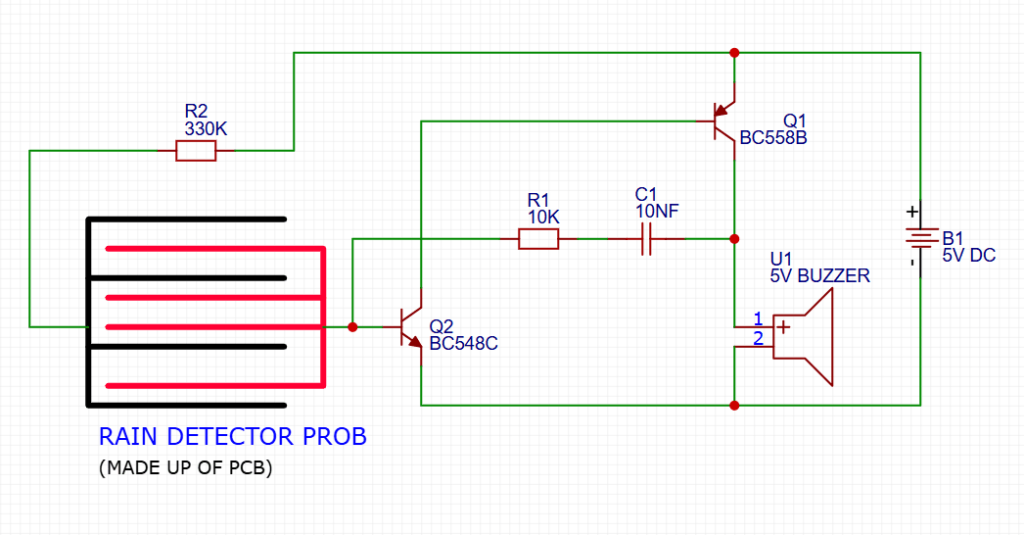
Rain Detector Working Principle
The black and red labeled sensor probe is made up of copper lines which is the main detector for the rain drops. When there’s no rain, the lines don’t touch electrically each other, so the circuit stays silent because of no conductivity across the lines.
When raindrops fall on the sensor, water connects the lines because water conducts the electricity. When water connects the lines, it sends a small signal into a BC548 transistor.
The transistor Q2 is like an automatic switch. When it sees this signal incoming to its base pin, it flips ON. The Resistor R1 and capacitor C1 help to smooth out the signal from Q2. This way, the circuit doesn’t get confused by a tiny splash or just a few drops.
The smooth signal now reaches to the base pin of transistor Q1. The Q1 also acts like a switch. When it gets the signal the electricity is flow to the buzzer. The buzzer turns ON and makes noise, alerting you that it’s raining. The whole system is runs on a 5V battery or power source, safe and easy to power with a USB or phone charger.