Are you looking for a simple and cost effective way to build a simple basic inverter circuit? This guide will explains you how to create a DIY inverter using a 555 timer IC, this is an essential project for electronics enthusiasts and hobbyists. We are using the NE555 timer IC and it is in astable mode of operation, so the circuit is efficiently converting the 12V DC supply into 230V AC using the step down transformer. Whether you’re experimenting with off-grid power solutions or learning how pulse width modulation (PWM) works in power electronics, this inverter circuit offers a practical and educational approach to low power AC generation at home in power outage conditions.
TIP31C Transistor Pinout
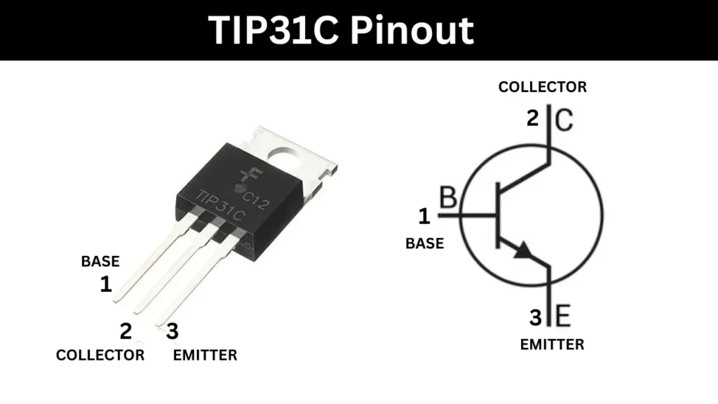
| Pin Number | Pin Name | Description |
|---|---|---|
| 1 | Base (B) | Input terminal used to control the transistor’s switching operation. |
| 2 | Collector (C) | Output terminal where the main current flows from collector to emitter. |
| 3 | Emitter (E) | Terminal connected to ground or negative rail; emits electrons to collector. |
Components Required
| Component | Value/Part Number | Quantity |
|---|---|---|
| 555 Timer IC | NE555P-HXY | 1 |
| Resistor | 1kΩ (R1) | 1 |
| Resistor | 100Ω (R3) | 1 |
| Potentiometer | 20kΩ (RP1) | 1 |
| Capacitor | 0.01µF (C1, C2) | 2 |
| Diode | 1N4007W (D1) | 1 |
| NPN Transistor | TIP31C (Q1, Q2) | 2 |
| Transformer | 12V-0-12V to 230V AC | 1 |
| Power Supply | 12V DC | 1 |
| Miscellaneous | Wires, Breadboard/PCB | – |
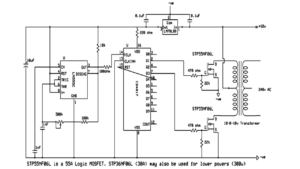
Circuit Diagram
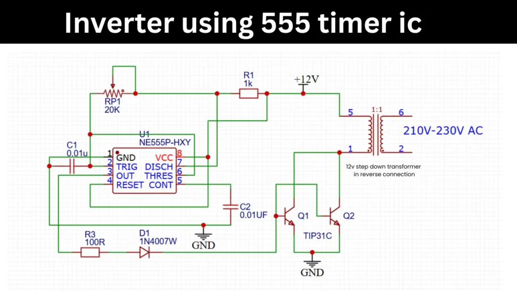
Construction and Working Principle
This circuit diagram is concit basic component as 555 timer IC. This circuit will converting the 12V DC voltage into 230V AC supply. The 555 timer is configured in astable mode and the IC will generating continuous square signal t the wave output pin of PIN3.
This output frequency of inverter can be adjustable using the 20kΩ potentiometer, which controls the charge and discharge timing of the capacitors connected to pins 6 and 2. The generated square wave signal is fed in to the base pin of two TIP31C NPN power transistors.
These transistors act as switches, it will switches the output current based on the frequency. Due to the fast switching effect in the 12V transformer coil creates a magnetic flux and mutual induction is happening.
Then the low voltage DC is converted into high-voltage AC (around 210V–230V) at the secondary winding of the transformer.
A 1N4007 diode is used for protection, and resistors and capacitors ensure stable operation and pulse shaping. This simple yet effective inverter is ideal for small electronics projects or as a basic backup power solution.
Applications
- Mini Backup Power Supply
- Low-Power Off-Grid Systems
- Low-Cost Inverter Development
- Useful in remote areas to run lightweight devices using a 12V battery.