Do you want to connect a relay with your microcontroller or any other IC? A simple 5V Relay Driver Circuit Using BC547 Transistor can do this. You can not connect the 5V relay directly to the microcontroller signal pin, because it can not have enough current to turn on the relay. So this BC547 based relay circuit can do this job.
Purpose of the Circuit
The main purpose of this relay circuit is to isolate the low power control electronics signals from high power loads by indirect way of power On and OFF. To amplify the input signal current, so the connected relay can be turned on easily. Also protect sensitive components from voltage spikes generated by the relay coil.
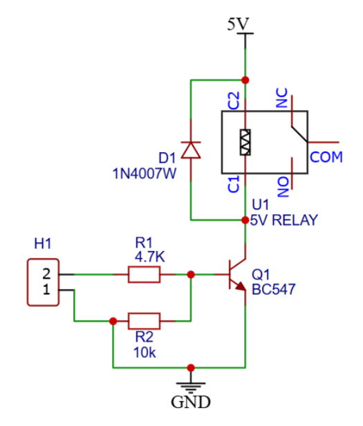
BC547 Relay Circuit Diagram
Components used
- U1 – 5V Relay: Electromechanical switch with COM, NO, and NC contacts.
- Q1 – BC547: NPN transistor used as a switch.
- D1 -1N4007 Diode: Flyback diode for protection.
- R1 – 4.7 kΩ: Base current limiting resistor.
- R2 – 10 kΩ: Pull-down resistor.
- H1: Input control header.
- 5V DC Power Supply.
Circuit Description
The 5V normal relay has 5 pins, 2 are coil connections and 3 pins for relay contacts. The relay coil is connected between the +5V power supply and the other end of the coil connection to the collector of the BC547 transistor. The emitter pin of the transistor is connected to ground supply.
The base of the transistor receives the control signal through connected resistor R1 of (4.7 kΩ), which limits the base current. The resistor R2 of 10 kΩ ensures the transistor remains OFF when there is no input signal is present.
Working Principle
If there is no base current flowing through the resistor then the transistor is in OFF state and relay also in OFF mode. Which means the relay contacts are not moving because no voltage across the relay coil, COM contact remains connected to NC.
If the Input voltage is applied in the H1 pins the transistor turns On and the current flows through the transistor easily. Which is called the saturation mode of the BC547 transistor. The relay coil get energized and turns ON the relay contacts.
Role of Flyback Diode of 1N4007
In the time of sudden ON and OFF of the relay coil, generating a high voltage spike due to its inductive nature. So this 1N4007 diode is protecting the transistor from high voltage damage. Using diodes with the relay increases the life of the circuit.
Applications
- Microcontroller based automation (Arduino, PIC, ESP).
- Home automation systems.
- Industrial control circuits.
- Alarm and security systems.
- Switching high voltage or high current devices safely.