A 2xAA sized battery can give exact 3V DC output in series connection, But in microcontroller projects and other sensor based projects this batteries can not be use for long time, because its charge will drain quick. So we need a dedicated 3V DC power supply circuit for continuous working without any problems. The circuit consist of a 230V AC to 6V DC steps down transformer, GBU406 bridge rectifier and LM317 adjustable voltage regulator IC. The circuit configuration will gives a stable 3V DC volt at output. This circuit is very useful for powering the small electronics device like LEDs, sensors, and microcontrollers.
Components Required
| Component | Specification/Value | Quantity |
|---|---|---|
| Transformer | 230V AC to 6V AC | 1 |
| Bridge Rectifier | GBU406 or 2A Bridge rectifier | 1 |
| Voltage Regulator | LM317 | 1 |
| Capacitor (Electrolytic) (C1, C3) | 100µF / 16V | 2 |
| Capacitor (Ceramic) (C2) | 0.01µF | 1 |
| Resistor (R3) | 1kΩ | 1 |
| Resistor (R2) | 470Ω | 1 |
| Resistor (R1, R4) | 330Ω | 2 |
| LED (Red) (LED1) | Standard 5mm | 1 |
| LED (Green) (LED2) | Standard 5mm | 1 |
| Output Terminal | 2 pin | 1 |
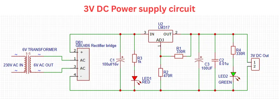
Circuit Diagram
Tools and Equipment Needed to Build the Circuit
| Tool/Equipment | Purpose |
|---|---|
| Soldering Iron | To solder components onto the PCB or veroboard |
| Solder Wire | For making electrical connections |
| Wire Cutter/Stripper | To cut and strip wires for connections |
| Multimeter | To test voltage, continuity, and connections |
| Screwdriver | For tightening terminal blocks and mounting |
| Needle-Nose Pliers | To bend leads and hold small components |
| PCB or Veroboard | Base for assembling the circuit |
| Heat Sink Compound | Improves heat transfer between LM317 and heatsink |
| Heat Sink | Helps cool down LM317 voltage regulator |
| AC Power Cord | To connect the transformer to 230V mains |
| Insulation Tape/Heat Shrink | For insulating exposed wires or joints |
Connection Explained
- The above given circuit a 20V Ac to 6V AC stepdown transformer is using to step down the high voltage AC current to low voltage.
- The Output connection of transformer is connected to the 4A bridge rectifier of GBU406, you can use 1N4007 based bridge rectifier incase of budget friendly circuit.
- This bridge rectifier circuit converting the pulsating 6V Ac to a pulsating 6V Dc output.
- 100µF/16V electrolytic capacitor is connected in the output pin of the bridge rectifier. This will smooths the pulsating DC from the rectifier and giving a steady DC voltage.
- Then the 6V DC is connected to the LM317 adjustable voltage regulator IC. This IC is delivering the 3V steady voltage in output. The output voltage is controlled by the Resistor R1 and R2 of 330Ω and 470Ω which is connected in the adjust pin of the IC.
- The Red LED (LED1) shows the input power is active and Green LED (LED2) shows the regulated 3V output is available.
- Capacitors C2 of 0.01µF and C3 of 100µF using as the high frequency filtering and provides a smoother output. At last From the 2 pin screw terminal we can take output volt of 3V DC.
Working Principle
- The 230V AC supply is connected to the primary side of the step down transformer. The transformer steps down the 230V AC voltage to 6V AC volt at the secondary.
- The bridge rectifier converting the 6V AC voltage into corresponding DC voltage with ripples.
- The Capacitor C1 smooths the rectified DC as a steady non pulsating voltage.
- The LM317 regulator connected with R1 and R2 which will sets the output to 3V DC at the out section.
- Capacitors C2 and C3 clean up any remaining noise or ripples and the LEDs show power status. Red = Input is on and Green = 3V DC Output is ready
- The output terminal delivers stable 3V DC for your electronics projects.
Voltage Calculation for 3V DC Output Using LM317
To calculates the output voltage of the LM317, this following formula is used,
Vout = 1.25V (1+R2/R1)
in the circuit diagram R1 = 330Ω and R2 = 470Ω, Then the output voltage will be calculated,
Vout = 1.25 (1+470/330)
Vout = 3.03V
Applications of the 3V DC Power Supply Circuit
- Powering 3V Electronic Devices like sensors, microcontrollers, and small modules.
- Ideal for driving red, green, or yellow LEDs that operate around 2-3V
- DIY Electronics Projects
- Embedded Systems Development
- The circuit is acts as a temporary replacement for 2xAA batteries
Tips for Building the 3V DC Power Supply Safely
- Use a Proper Heat Sink on the LM317 voltage regulator IC o prevent overheating and extends the regulator’s life.
- Double check the connection polarity of the capacitor, LEDs, and power connections is correct to avoid damage.
- Always test the circuit with a Multimeter to see output voltage with and input voltage.
- The input side is connected to the mains electricity. So Be very careful or use an isolation transformer while testing.
- Add a small fuse on the primary side of the transformer to protect against short circuits.
- For a stable and durable build, assemble the components on a proper board instead of a breadboard.