Your main supply gone but you don’t know about this, may be this is happened due to by your mains supply fuse. If the main fuse blown the electricity will not pass through it. In this article I’m sharing very simple and easiest circuit to detecting the AC blown fuse by using this indicator circuit. This simple blown fuse indicator circuit using LEDs as visual indicator, this is a perfect solution.
It visually alerts you with a red LED when the fuse is blown and a green LED when everything is working fine. Ideal for home appliances and DIY electrical projects, this circuit enhances safety by providing a clear status of fuse operation. The circuit is designed with minimal components, including resistors and LEDs, it ensures low cost and high efficiency. Learn how this AC fuse failure indicator works and how to build it.
Components Required
| Component | Specification/Value | Quantity |
|---|---|---|
| AC Power Source | 220V AC | 1 |
| Fuse | X1 (Standard AC Fuse) | 1 |
| LED1 (Green) | 5mm, 20mA | 1 |
| LED2 (Red) | 5mm, 20mA | 1 |
| Resistor R2 | 47kΩ, 0.5W or 1W | 1 |
| Resistor R3 | 47kΩ, 0.5W or 1W | 1 |
| Connecting Wires | – | As required |
| Breadboard/PCB | – | 1 |
Circuit diagram
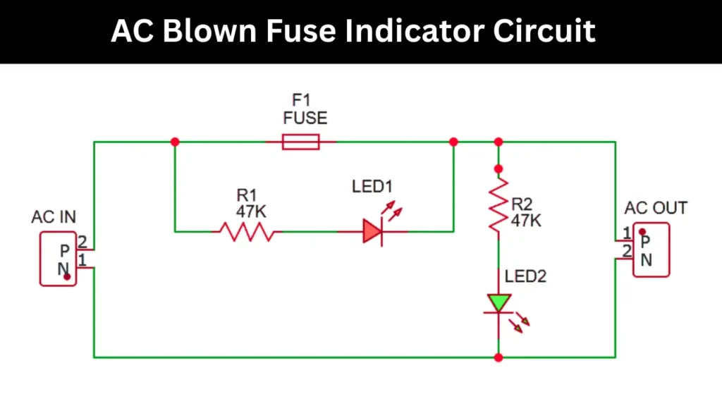
Construction and Working Principle
This circuit basic working principle is glowing Red LED when the fuse blown in any conditions. The connected two LED indicating the sign of connection Red means fuse broken and green means all is good working condition. so hear i am explaining how it all works in different conditions.
Normal Operation
- When the fuse (F1) is intact, the 220V AC supply flows through the fuse to the AC out.
- In this condition the LED2 lights up through resistor resistor R2 (47kΩ) and it indicating the circuit is working properly and the fuse is not blown.
- LED1 (Red) does not light up because it has no voltage drop across it due to the low potential difference on both sides (as the fuse is conducting).
Blown Fuse Condition
- If the fuse blows (opens the circuit) then the the supply to the AC out is cut off.
- However, the return path is still available through resistor R3 (47kΩ) and LED1.
- As a result the LED1 turns on and it indicating that the fuse is blown.
- LED2 turns off since there is no current flowing through R2 and the load side.