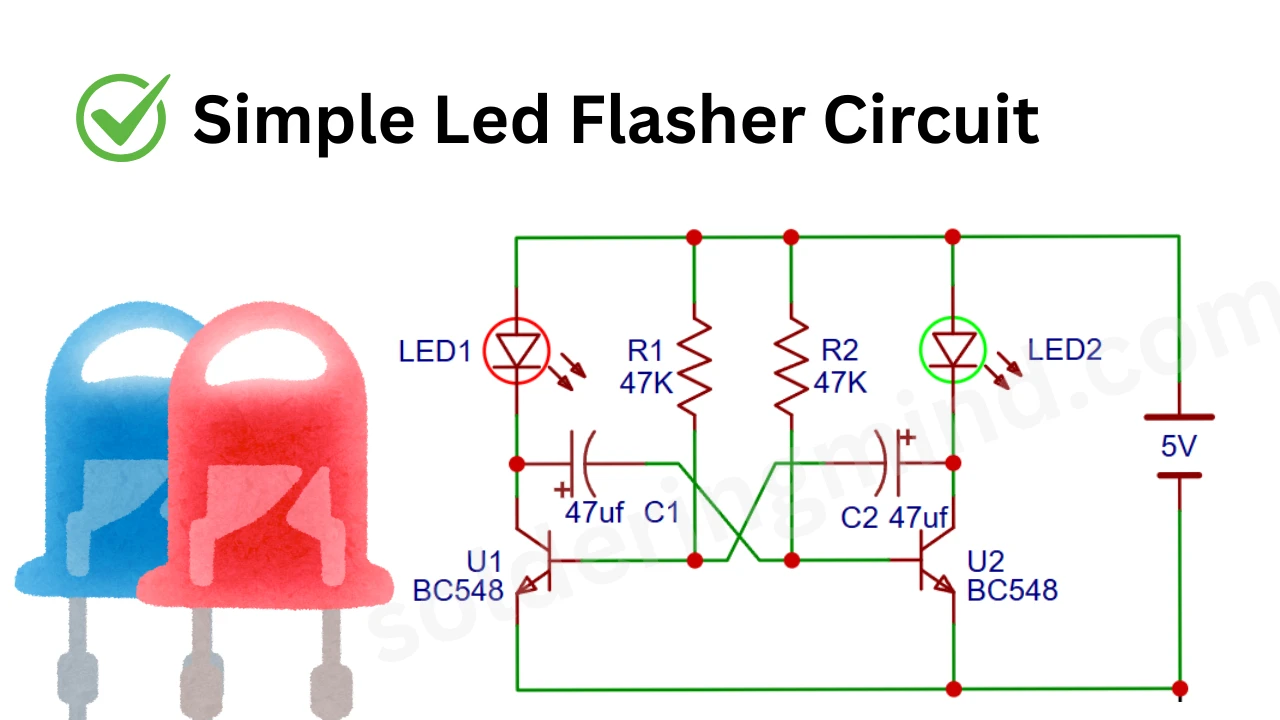
Looking for a simple yet effective LED flasher circuit? This easy to build astable multivibrator using two BC548 transistors is a perfect beginner friendly electronics project. Powered by a 5V DC supply, this circuit alternately flashes two LEDs using just a few common components like resistors, capacitors, and NPN transistors. Whether you’re learning basic electronics or creating eye catching LED effects, this blinking LED circuit offers a great foundation for understanding transistor switching and timing.
Components Required
| Component | Specification/Value | Quantity |
|---|---|---|
| NPN Transistor | BC548 | 2 |
| Resistor | 47kΩ | 2 |
| Capacitor (Electrolytic) | 47µF, 16V (or higher) | 2 |
| LED | Red/Green or any color | 2 |
| Power Supply | 5V DC | 1 |
| Breadboard/PCB | As needed | 1 |
| Connecting Wires | – | As needed |
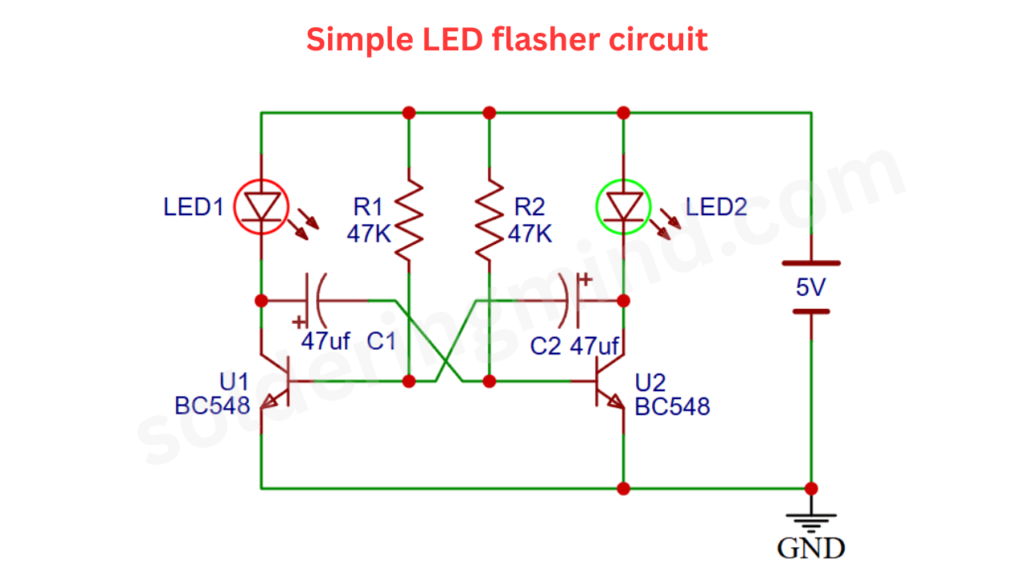
Circuit Diagram
Construction
This LED flasher circuit is built around two NPN transistors (BC548), configured in an astable multivibrator setup. Each transistor has a 47kΩ resistor connected between its collector and the positive rail, and a 47µF electrolytic capacitor connected between the collector of one transistor and the base of the other. Two LEDs are placed in series with each transistor’s collector, with the cathodes going to the collectors and anodes connected to the positive supply. The entire circuit is powered by a 5V DC source. This symmetric arrangement ensures alternating switching action.
Working
When power is applied, the two transistors start switching ON and OFF alternately, causing the LEDs to blink one after the other. The capacitors charge and discharge through the base of the opposite transistor, creating a feedback loop that keeps the circuit oscillating. When one transistor turns ON, it lights up its corresponding LED and keeps the other transistor OFF. As the capacitor discharges, the states flip, and the other LED lights up. This process repeats continuously, producing a simple and effective blinking LED pattern ideal for learning transistor switching and timing applications.